


2G6
(10) The heater lamp does not turn off. ............................................................................................... 1-5-19
(11) Main charging is not performed. ................................................................................................... 1-5-19
(12) Transfer charging is not performed. ............................................................................................. 1-5-19
(13) A paper jam in the paper feed or exit section is indicated
when the power switch is turned on. ............................................................................................ 1-5-19
(14) The LED indicator requesting covers to be closed is displayed
when the front cover is closed. ..................................................................................................... 1-5-20
(15) Others. .......................................................................................................................................... 1-5-20
1-5-5 Mechanical problems ......................................................................................................................... 1-5-21
(1) No primary paper feed. ................................................................................................................. 1-5-21
(2) No secondary paper feed. ............................................................................................................ 1-5-21
(3) Skewed paper feed. ..................................................................................................................... 1-5-21
(4) Multiple sheets of paper are fed at one time. ................................................................................ 1-5-21
(5) Paper jams. .................................................................................................................................. 1-5-21
(6) Abnormal noise is heard. ............................................................................................................. 1-5-21
1-6 Assembly and Disassembly
1-6-1 Precautions for assembly and disassembly ......................................................................................... 1-6-1
(1) Precautions .................................................................................................................................... 1-6-1
1-6-2 Removing the process unit .................................................................................................................. 1-6-2
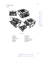
1-6-3 Removing the principal outer covers ................................................................................................... 1-6-3
(1) Removing the top cover/output tray ............................................................................................... 1-6-3
(2) Removing the right cover ............................................................................................................... 1-6-4
(3) Removing the left cover .................................................................................................................. 1-6-4
1-6-4 Removing the feed roller ...................................................................................................................... 1-6-5
1-6-5 Removing the MP feed roller ............................................................................................................... 1-6-6
1-6-6 Removing the transfer roller ................................................................................................................. 1-6-8
1-6-7 Removing the principal PWBs ............................................................................................................. 1-6-9
(1) Removing the engine PWB ............................................................................................................ 1-6-9
(2) Removing the main PWB ............................................................................................................. 1-6-10
(3) Removing the power supply unit and high voltage unit ................................................................ 1-6-12
(4) Removing the bias PWB .............................................................................................................. 1-6-13
1-6-8 Removing the main motor and drive unit ........................................................................................... 1-6-15
1-6-9 Removing and splitting the fuser unit ................................................................................................. 1-6-19
(1) Removing the separation craws ................................................................................................... 1-6-21
(2) Removing the heater lamp ........................................................................................................... 1-6-22
(3) Removing the heat roller .............................................................................................................. 1-6-23
(4) Removing the fuser thermistor ..................................................................................................... 1-6-25
(5) Removing the thermal cutout ....................................................................................................... 1-6-26
(6) Removing the press roller ............................................................................................................ 1-6-27
1-6-10 Removing the laser scanner unit and the eraser lamp ...................................................................... 1-6-28
1-6-11 Removing the main charger unit ........................................................................................................ 1-6-31
1-7 Upgrading the firmware
1-7-1 Upgrading the firmware on the main PWB .......................................................................................... 1-7-1
(1) Firmware program data format ....................................................................................................... 1-7-1
(2) Downloading the firmware from the parallel interface .................................................................... 1-7-2
(3) Downloading the firmware from the memory card ......................................................................... 1-7-3
(4) Downloading errors ........................................................................................................................ 1-7-4
2-1 Mechanical construction
2-1-1 Paper feeding system .......................................................................................................................... 2-1-1
(1) Paper feed control .......................................................................................................................... 2-1-2
(2) Paper feeding mechanism ............................................................................................................. 2-1-3
(3) Switchback/refeed system .............................................................................................................. 2-1-4
2-1-2 Electrophotographic system ................................................................................................................. 2-1-6
(1) Electrophotographic cycle .............................................................................................................. 2-1-6


