background image

5JR

1-3-9

U611

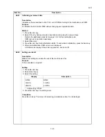
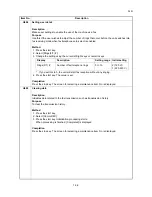
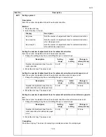
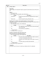
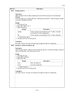
Setting system 2

Description

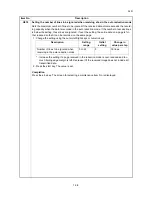
Sets the number of adjustment lines for automatic reduction.

Method

1. Press the start key.
2. Select the item to be set.

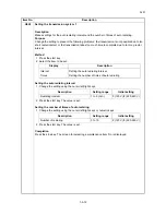
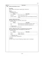
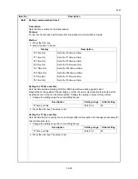
Setting the number of adjustment lines for automatic reduction

Sets the number of adjustment lines for automatic reduction.

1. Change the setting using the cursor left/right keys or numeric keys.

2. Press the start key. The value is set.

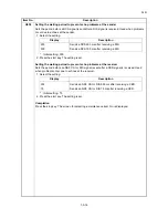
Setting the number of adjustment lines for automatic reduction when A4 paper is set

Sets the number of adjustment lines for automatic reduction when A4 paper is set.

1. Change the setting using the cursor left/right keys or numeric keys.

2. Press the start key. The value is set.

Setting the number of adjustment lines for automatic reduction when letter size paper is 
set

Sets the number of adjustment lines for automatic reduction when letter size paper is set.

1. Change the setting using the cursor left/right keys or numeric keys.

2. Press the start key. The value is set.

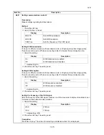
Completion

Press the stop key. The screen for selecting a maintenance item No. is displayed.

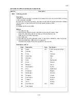
Item No.

Description

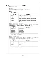
Display

Description

Adj Lines

Sets the number of adjustment lines for automatic reduction.

Adj Lines(A4)

Sets the number of adjustment lines for automatic reduction 
when A4 paper is set.

Adj Lines(LT)

Sets the number of adjustment lines for automatic reduction 
when letter size paper is set.

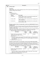
Description

Setting 

range

Initial 

setting

Change in 

value per step

Number of adjustment lines for auto-
matic reduction

0 to 22

7

16 lines

Description

Setting 

range

Initial 

setting

Change in 

value per step

Number of adjustment lines for auto-
matic reduction when A4 paper is set

0 to 22

22

16 lines

Description

Setting 

range

Initial 

setting

Change in 

value per step

Number of adjustment lines for auto-
matic reduction when letter size paper 
is set

0 to 26

26

16 lines

Содержание Fax System (U)

Страница 1: ...SERVICE MANUAL Published in October 2010 845JR110 5JRSM060 First Edition FAX System U ...

Страница 2: ...ficials for details in your area for proper disposal ATTENTION IL Y A UN RISQUE D EXPLOSION SI LA BATTERIE EST REMPLACEE PAR UN MODELE DE TYPE INCORRECT METTRE AU REBUT LES BATTERIES UTILISEES SELON LES INSTRUCTIONS DONNEES Il peut être illégal de jeter les batteries dans des eaux d égout municipales Vérifiez avec les fonctionnaires municipaux de votre région pour les détails concernant des déchet...

Страница 3: ...Revision history Revision Date Replaced pages Remarks ...

Страница 4: ...This page is intentionally left blank ...

Страница 5: ...rsonnel to ensure the safety of their customers their machines as well as themselves during maintenance activities Service personnel are advised to read this booklet carefully to familiarize themselves with the warnings and precautions described here before engaging in maintenance activities ...

Страница 6: ... this symbol CAUTION Bodily injury or damage to property may result from insufficient attention to or incorrect com pliance with warning messages using this symbol Symbols The triangle symbol indicates a warning including danger and caution The specific point of attention is shown inside the symbol General warning Warning of risk of electric shock Warning of high temperature indicates a prohibited...

Страница 7: ...d or dusty place This may cause fire or electric shock Do not install the copier near a radiator heater other heat source or near flammable material This may cause fire Allow sufficient space around the copier to allow the ventilation grills to keep the machine as cool as possible Insufficient ventilation may cause heat buildup and poor copying performance Always handle the machine by the correct ...

Страница 8: ... carefully Always check that the copier is correctly connected to an outlet with a ground connection Check that the power cable covering is free of damage Check that the power plug is dust free If it is dirty clean it to remove the risk of fire or electric shock Never attempt to disassemble the optical unit in machines using lasers Leaking laser light may damage eyesight Handle the charger section...

Страница 9: ...r trapped wire and missing screws Check that all the caution labels that should be present on the machine according to the instruction handbook are clean and not peeling Replace with new ones if necessary Handle greases and solvents with care by following the instructions below Use only a small amount of solvent at a time being careful not to spill Wipe spills off completely Ventilate the room wel...

Страница 10: ...This page is intentionally left blank ...

Страница 11: ...ification 1 4 2 2 1 U004XX error code table Interrupted phase B 1 4 4 2 2 U006XX error code table Problems with the unit 1 4 4 2 3 U008XX error code table Page transmission error 1 4 4 2 4 U009XX error code table Page reception error 1 4 4 2 5 U010XX error code table G3 transmission 1 4 5 2 6 U011XX error code table G3 reception 1 4 6 2 7 U017XX error code table V 34 transmission 1 4 7 2 8 U018XX ...

Страница 12: ...5JR This page is intentionally left blank ...

Страница 13: ...ent feed Max 50 sheets Only Model with Document Processor as standard Scanner resolution Horizontal Vertical 200 100 dpi Normal 8 dot mm 3 85 line mm 200 200 dpi Fine 8 dot mm 7 7 line mm 200 400 dpi Super fine 8 dot mm 15 4 line mm 400 400 dpi Ultra fine 16 dot mm 15 4 line mm Printing resolution 600 600 dpi Gradations 256 shades Error diffusion One Touch key 100 keys Multi Station transmission M...

Страница 14: ...lementary communica tion functions Manual send Address book Canceling communication Line monitor Transmission destination display Tone transmission Memory back up Printing out from FAX box subaddress based confidential reception Communication result display Batch transmission TTI transmission Bulletin board communication function Rotation transmission Duplex transmission 2 Initial communication sp...

Страница 15: ...rt Receipt result report Activity report Status page Network FAX Addition of a cover page E mail reporting of the transmission result Terminal service File name Others Cancelling and sending delayed transmissions queued Remote diagnosis Smoothing reception Fax priority printout Common address for the machine and FAX ...

Страница 16: ...ote that you cannot automatically receive FAX when turning the main power switch off To turn the power off press the Power key on the operation panel 2 4 5 3 1 1 Operation panel 2 Main power switch 3 Controller box cover 4 LINE Connector 5 TEL Connector ...

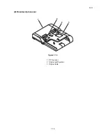
Страница 17: ...5JR 1 1 5 2 Document processor Figure 1 1 2 2 1 2 3 1 DP top cover 2 Original width guides 3 Original table ...

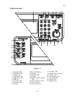
Страница 18: ...t key LED 5 Enagy saver LED 6 Reset key 7 Power key LED 8 Main power LED 9 Clear key 10 Quick No serch key 11 Enter key 12 Start key LED 13 Stop key 14 System menu Counter key LED 15 Status Job cancel LED 16 Copy key LED 17 Favorite key LED 18 Send key LED 19 Document box key LED 20 FAX key LED 21 Job separator LED 22 Processing LED 23 Memory LED 24 Attention LED ...

Страница 19: ...humidity or low temperature and low humidity an abrupt change in the environmental temperature and cool or hot direct air Avoid places subject to dust and vibrations Choose a surface capable of supporting the weight of the machine Place the machine on a level surface maximum allowance inclination 1 Avoid air borne substances that may adversely affect the machine or degrade the photoconductor such ...

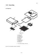
Страница 20: ... 1 Caution See the Installation Guide for installation 9 6 7 5 4 1 3 2 8 1 Fax assembly 2 Plastic bag 3 Air padded bag 4 Modular cord 1 5 Plastic bag 6 Outer case 7 Installation guide 8 Alphabet label 9 Plastic bag 1 120 V and Australian models only ...

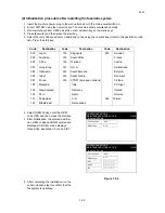
Страница 21: ...ed A ROM version displays three kinds application boot and IPL Figure 1 2 2 8 After completing the installation run the communications test to confirm that the fax system is operative Code Destination Code Destination Code Destination 000 Japan 156 Singapore 253 Sweden 009 Australia 159 South Africa France 038 China 169 Thailand Austria 080 Hong Kong 181 U S A Switzerland 084 Indonesia 242 South A...

Страница 22: ...5JR 1 2 4 This page is intentionally left blank ...

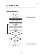
Страница 23: ...maintenance item number using the cursor left right keys or numeric keys The selected maintenance item is run Press the stop key Press the start key Start End Maintenance mode is entered The maintenance item is selected Maintenance mode is exited and the system is restarted to initialize it and to reflect the setting changes Repeat the same maintenance item Run another maintenance item Turn the ma...

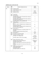
Страница 24: ...when A4 paper is set Setting the number of adjustment lines for automatic reduc tion when letter size paper is set 7 22 26 U612 Setting system 3 Selecting if auto reduction in the auxiliary direction is to be performed Setting the automatic printing of the protocol list On Off U615 Setting system 6 Ledger U620 Setting the remote switching mode One U625 Setting the transmission system 1 Setting the...

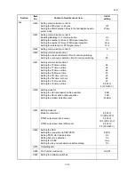
Страница 25: ...ting the T2 time out time Setting the Ta time out time Setting the Tb1 time out time Setting the Tb2 time out time Setting the Tc time out time Setting the Td time out time 56 36 69 30 20 80 60 9 120 V 6 220 240 V U650 Setting modem 1 Setting the G3 transmission cable equalizer Setting the G3 reception cable equalizer Setting the modem detection level 0dB 0dB 43dBm U651 Setting modem 2 Modem outpu...

Страница 26: ...ion code list on following for the destination code OEM code is no operation necessary 3 Select Execute 4 Press the start key Data initialization starts To cancel data initialization press the stop key 5 After data initialization ROM version are displayed A ROM version displays three kinds application boot and IPL Destination code list Code Destination Code Destination 000 Japan 253 CTR21 European...

Страница 27: ...xecute 4 Press the start key Data initialization starts To cancel data initialization press the back key 5 After data initialization ROM version are displayed A ROM version displays three kinds application boot and IPL U603 Setting user data 1 Description Makes user settings to enable the use of the machine as a fax Purpose To be executed as required Setting 1 Press the start key 2 Select Line Typ...

Страница 28: ...nging 4 Press the start key The value is set Completion Press the stop key The screen for selecting a maintenance item No is displayed U605 Clearing data Description Initializes data related to the fax transmission such as transmission history Purpose To clear the transmission history Method 1 Press the start key 2 Select Comm REC 3 Press the start key Initialization processing starts When process...

Страница 29: ...r of lines to be ignored when receiving a fax at 100 magnification Sets the maximum number of lines to be ignored if the received data volume exceeds the record ing capacity when recording the data at 100 magnification If the number of excess lines is below the setting those lines are ignored If over the setting they are recorded on the next page 1 Change the setting using the cursor left right ke...

Страница 30: ... that it can be recorded on the same page 1 Change the setting using the cursor left right keys or numeric keys Increase the setting if a page received in the reduction mode is over reduced and too much trailing edge margin is left Decrease it if the received image does not include all transmitted data 2 Press the start key The value is set Completion Press the stop key The screen for selecting a ...

Страница 31: ...reduction when letter size paper is set 1 Change the setting using the cursor left right keys or numeric keys 2 Press the start key The value is set Completion Press the stop key The screen for selecting a maintenance item No is displayed Item No Description Display Description Adj Lines Sets the number of adjustment lines for automatic reduction Adj Lines A4 Sets the number of adjustment lines fo...

Страница 32: ... is automatically printed out 1 Select the setting using the cursor left right keys Initial setting Off 2 Press the start key The setting is set Completion Press the stop key The screen for selecting a maintenance item No is displayed Item No Description Display Description Auto Reduct Selects if auto reduction in the auxiliary direction is to be per formed Protocol List Sets the automatic printin...

Страница 33: ...splayed U620 Setting the remote switching mode Description Sets the signal detection method for remote switching Be sure to change the setting according to the type of telephone connected to the machine Setting 1 Press the start key 2 Select Remort Mode 3 Select the mode Initial setting One 4 Press the start key The setting is set Completion Press the stop key The screen for selecting a maintenanc...

Страница 34: ...1 Change the setting using the cursor left right keys 2 Press the start key The value is set Setting the number of times of auto redialing 1 Change the setting using the cursor left right keys or numeric keys 2 Press the start key The value is set Completion Press the stop key The screen for selecting a maintenance item No is displayed Item No Description Display Description Interval Setting the a...

Страница 35: ...sender is informed of using the DIS or NSF signal When the destination unit has V 34 capability V 34 is selected regardless of the setting 1 Select the setting Initial setting 14400bps 2 Press the start key The setting is set Item No Description Display Description TX Speed Sets the communication starting speed RX Speed Sets the reception speed TX Echo Sets the waiting period to prevent echo probl...

Страница 36: ...he period before an NSF CSI or DIS signal is sent after a CED signal is received Used when problems occur due to echoes at the receiver 1 Select the setting Initial setting 75 2 Press the start key The setting is set Completion Press the stop key The screen for selecting a maintenance item No is displayed Item No Description Display Description 500 Sends a DCS 500 ms after receiving a DIS 300 Send...

Страница 37: ...the IP Internet Protocol telephone line 1 Select the setting Initial setting On 2 Press the start key The setting is set Setting the frequency of the CED signal Sets the frequency of the CED signal Used as one of the measures to improve transmission per formance for international communications 1 Select the setting Initial setting 2100 2 Press the start key The setting is set Completion Press the ...

Страница 38: ...elect mode Sets the CNG detection times in the fax telephone auto select mode 1 Select the setting Initial setting 2Time 2 Press the start key The setting is set Completion Press the stop key The screen for selecting a maintenance item No is displayed Item No Description Display Description DIS 4Byte Sets the DIS signal to 4 bytes Num OF CNG F T Sets the CNG detection times in the fax telephone au...

Страница 39: ...bol speed 3429 Hz is used 1 Select the setting Initial setting On 2 Press the start key The setting is set Item No Description Display Description V 34 Enables or disables V 34 communication V 34 3429Hz Sets the V 34 symbol speed 3429 Hz DIS 2Res Sets the number of times of DIS signal reception RTN Check Sets the reference for RTN signal output Display Description On V 34 communication is enabled ...

Страница 40: ...reen for selecting a maintenance item No is displayed U634 Setting communication control 5 Description Sets the maximum number of error bytes judged acceptable when receiving a TCF signal Used as a measure to ease transmission conditions if transmission errors occur Setting 1 Press the start key 2 Select TCF Check 3 Change the setting using the cursor left right keys or numeric keys 4 Press the st...

Страница 41: ...e setting using the cursor left right keys 2 Press the start key The value is set Setting the continuous detection time for remote switching 1 Change the setting using the cursor left right keys 2 Press the start key The value is set Completion Press the stop key The screen for selecting a maintenance item No is displayed Item No Description Display Description Time One Sets the one shot detection...

Страница 42: ...t keys 2 Press the start key The value is set Setting the T1 time out time Sets the time before receiving the correct signal after call reception No change is necessary for this maintenance item 1 Change the setting using the cursor left right keys 2 Press the start key The value is set Item No Description Display Description T0 Time Out Sets the T0 time out time T1 Time Out Sets the T1 time out t...

Страница 43: ... fails to receive a call 1 Change the setting using the cursor left right keys 2 Press the start key The value is set Figure 1 3 1 Ta Tb1 Tb2 time out time Setting the Tb1 time out time In the fax telephone auto select mode sets the time to start sending the ring back tone after receiving a call as a fax machine see figure 1 3 1 In fax telephone auto select mode change the setting when fax recepti...

Страница 44: ...sful or a telephone fails to receive a call 1 Change the setting using the cursor left right keys 2 Press the start key The value is set Setting the Td time out time Sets the length of the time required to determine silent status fax one of the triggers for Tc time check In the TAD mode change the setting when fax reception is unsuccessful or a telephone fails to receive a call Be sure not to set ...

Страница 45: ...ing 0dB 2 Press the start key The setting is set Setting the G3 reception cable equalizer 1 Select 0dB 4dB 8dB or 12dB Initial setting 0dB 2 Press the start key The setting is set Setting the modem detection level 1 Select 33dBm 38dBm 43dBm or 48dBm using the cursor up down keys Initial setting 43dBm 2 Press the start key The setting is set Completion Press the stop key The screen for selecting a ...

Страница 46: ...3 Change the setting using the cursor left right keys or numeric keys 4 Press the start key The setting is set Completion Press the stop key The screen for selecting a maintenance item No is displayed Item No Description Display Description Setting range Initial setting Sgl LV Mdm Modem output level 1 to 15 9 120 V 10 220 240 V DTMF LV C DTMF output level main value 0 to 15 0 5 120 V 10 5 220 240 ...

Страница 47: ...cts if the dial tone is detected to check the telephone is off the hook when a fax is connected to a public switched telephone network 1 Select the setting Initial setting On 2 Press the start key The setting is set Item No Description Display Description Exchange Sets the connection to PBX PSTN Dial Tone Sets PSTN dial tone detection Busy Tone Sets busy tone detection PBX Setting Setting for a PB...

Страница 48: ... an outside call when connected to a PBX According to the type of the PBX connected select the mode to connect an outside call 1 Select the setting Initial setting Loop 2 Press the start key The setting is set Setting the loop current detection before dialing Sets if the loop current detection is performed before dialing 1 Select the setting Initial setting On 2 Press the start key The setting is ...

Страница 49: ...tenance item No is displayed Item No Description Display Description Sys Conf Report Outputs a list of software switches self telephone number confidential boxes ROM versions and other information Action List Outputs a list of error history transmission line details and other information Self Sts Report Outputs a list of settings in maintenance mode own status report regarding fax transmission onl...

Страница 50: ...Select On or Off using the cursor left right keys Initial setting Off 2 Press the start key The setting is set Completion Press the stop key The screen for selecting a maintenance item No is displayed Item No Description Display Description FAX Bulk TX fax batch transmission On Off A5 Pt Pri Chg Change of print size priority at the time of small size reception Display Description On Fax batch tran...

Страница 51: ...tween 0 and 1 5 Press the start key to set the value Completion Press the stop key The screen for selecting a maintenance item No is displayed List of Software Switches of Which the Setting Can Be Changed Communication control procedure Item No Description No Bit Item 36 7654 Coding format in transmission 3210 Coding format in reception 37 5 33600 bps V34 4 31200 bps V34 3 28800 bps V34 2 26400 bp...

Страница 52: ...ction pattern 122 7654 Busy tone detection pattern 1 Busy tone detection in automatic FAX TEL switching 125 76543210 Access code registration for connection to PSTN 126 7654 FAX TEL automatic switching ring back tone ON OFF cycle No Bit Item 133 76543210 DTMF signal transmission time 134 76543210 DTMF signal pause time 141 76543210 Ringer detection cycle minimum 142 76543210 Ringer detection cycle...

Страница 53: ...ation errors start with an E indica tion followed by five digits The upper three of the five digits indicate general classification of the error and its cause while the lower two indicate the detailed classification Items for which detailed classification is not necessary have 00 as the last two digits Figure 1 4 1 Error code U X X X X X Detailed classification of error code General classification...

Страница 54: ...on in V 34 mode refer to 1 4 7 U017XX error code table U018XX A communication error occurred before starting T 30 protocol during reception in V 34 mode refer to 1 4 7 U018XX error code table U03000 No document was present in the destination unit when polling reception started U03200 In interoffice subaddress based bulletin board reception data was not stored in the box specified by the destinatio...

Страница 55: ...ssword check reception or restricted reception was interrupted because the permit ID s did not match the rejected FAX number s did match or the destination receiver did not return its phone number U05300 The password check reception or the restricted reception was interrupted because the permitted numbers did not match the rejected numbers did match or the machine in question did not acknowledge i...

Страница 56: ...ss based confidential reception was interrupted because the specified subad dress box was not registered U00450 The destination transmitter disconnected because the permit ID s did not agree with while the destination transmitter is in password check transmission or restricted trans mission U00460 Encrypted reception was interrupted because the specified encryption box number was not registered U0...

Страница 57: ...mand retransfers was exceeded ECM U01022 No relevant signal was received after transmission of an RR signal and the preset num ber of command retransfers was exceeded ECM U01028 T5 time out was detected during ECM transmission ECM U01052 A DCN signal was received after transmission of an RR signal ECM U01080 A PIP signal was received after transmission of a PPS NULL signal U01092 During transmissi...

Страница 58: ...U01141 A DCN signal was received after transmission of a DTC signal U01143 A DCN signal was received after transmission of an FTT signal U01155 A DCN signal was received after transmission of an SPA signal short protocol U01160 During message reception transmission time exceeded the maximum transmission time per line U01162 Reception was aborted due to a modem malfunction during message reception ...

Страница 59: ... device training For example INFO0 B Bbar A Abar for polling reception probing tone was not detected U01810 A communication error that occurs at the receiver unit in phase 3 primary channel equivalent device training For example S Sbar PP TRN was not detected U01820 A communication error that occurs at the receiver unit in the period after initiating the control channel before entering the T 30 pr...

Страница 60: ...5JR 1 4 8 This page is intentionally left blank ...

Страница 61: ...ol PWB any normal communication com mand is not transmitted Defective FAX soft ware Install the fax software Defective FAX con trol PWB Replace the fax control PWB and check for correct operation 0830 FAX control PWB flash pro gram area checksum error A checksum error occurred with the program of the FAX control PWB Defective FAX soft ware Install the fax software Defective FAX con trol PWB Replac...

Страница 62: ...5JR 1 5 2 This page is intentionally left blank ...

Страница 63: ...as the firm ware in the USB memory slot 3 Turn ON the main power switch 4 About 50 seconds later FW Update will be displayed and blinking the data LED this shows to start the download 5 Display the software that now upgrad ing Figure 1 6 1 SAMPLE Firmware Update The first line Display shown while updating it FAX The second line Display that shows update object xxx The third line The progress of th...

Страница 64: ...5JR 1 6 2 This page is intentionally left blank ...

Страница 65: ...5JR 2 1 1 2 1 Electrical Parts Layout 2 1 1 Electrical parts layout Figure 2 1 1 1 Fax control PWB FCPWB Modulates demodulates compresses and decompresses 1 ...

Страница 66: ...5JR 2 1 2 This page is intentionally left blank ...

Страница 67: ... Ground 3 RESETN I 0 3 3 V DC Reset signal 4 VDD5_CUT I 5 V DC Control voltage 5 GND Ground 6 WAKEUP O 0 3 3 V DC Wake up signal 7 AUDIO O Analog Audio signal 8 NC Not used 9 MODE I 0 5 V DC Mode signal 10 S_RESET I 0 5 V DC Reset signal 11 GND Ground 12 NC Not used 13 NC Not used 14 GND Ground 15 NC Not used 16 NC Not used 17 GND Ground 18 USB_DP I O USB D 19 USB_DN I O USB D 20 VBUS I 5 V DC 5 V...

Страница 68: ...5JR 2 2 2 This page is intentionally left blank ...

Страница 69: ......

Страница 70: ......

Отзывы: