

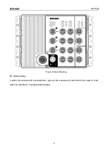


Connection
14
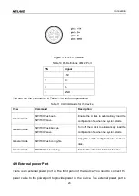
Note:
"+" and "-" indicate level polarities.
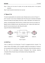
Wiring Sequence
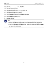
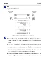
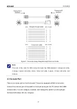
Figure 8 Connection Using Straight-through/Cross-over Cable
Note:
The color of the cable for RJ45 connector meets the 568B standard: 1-orange and white,
2-orange, 3-green and white, 4-blue, 5-blue and white, 6-green, 7-brown and white, and
8-brown.
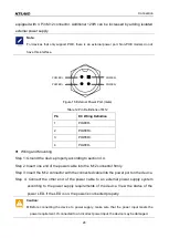
The 1 and 3, 2 and 4 pins on the M12 interface are differentiated signal pins in pairs. The
orange-and-white and orange pair, green-and-white and green pair, blue-and-white and blue
pair, and brown-and-white and brown pair in twist pair cables must be used in correct pairs
while being connected with the signal pins. For example, the above figure, the
orange-and-white and orange and green-and-white and green pairs are used.
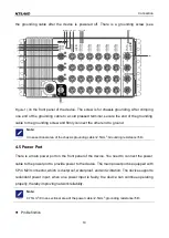
POE ports will not deliver any power for a certain time when a 10ms interruption occurs on the
power input. A suggested workaround is to connect a UPS to prevent power interruption of the