


OPERATING INSTRUCTIONS
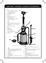
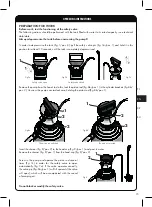
DEVICE ASSEMBLY
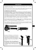
Do not remove the head (fig. 2/pos. 1) from the tank (fig. 2/pos. 2).
Fig.2
1
2
Screw the hose assembly (fig. 4a) to the device head (fig. 4b), making sure that the connection is airtight.
Fig.4b
Connect the suction tube provided
(fig. 3/pos. 1) to the hose connector
(fig. 3/pos. 2).
2
Fig.4a
1
Fig.3
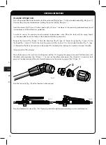
Fig.5
1
2
Fig.6
Attach the shoulder strap - adjust length as needed.
EN
PL
3
14
RU
DE
Make sure that the piston valve body (fig. 5/pos. 2)
is fitted with an o-ring (fig. 5/pos. 3)
and screw it onto the lance (fig. 5/pos. 1)
to achieve a tight connection.
Содержание 20010234
Страница 29: ...1 2 3 4 5 6 7 8 9 10 1 1 12 13 14 15 16 17 18 19 20 21 22 23 3 RU EN DE PL 29...
Страница 30: ...RU EN PL DE 2 1 2 2 2 1 2 4 4 4 3 1 3 2 2 4a 1 3 5 1 2 6 3 30 5 2 ring 5 3 5 1...
Страница 31: ...RU EN DE PL 1 7a 7 7c 8 1 8 2 8 1 1 8 7a 1 10 8a 8 2 1 2 1 9 2 9 1 9 1 9 2 7c 7a 7a 1 9 2 1 3 3 31...
Страница 32: ...10 2 1 RU EN PL DE 8 1 8 2 8 1 9 2 9 1 9 1 9 2 1 5 1 4 8 1 8 2 7 20 7 1 7 1 12 3 10 1 1b 12 3 1 1a 1 1 32...


