4
r.
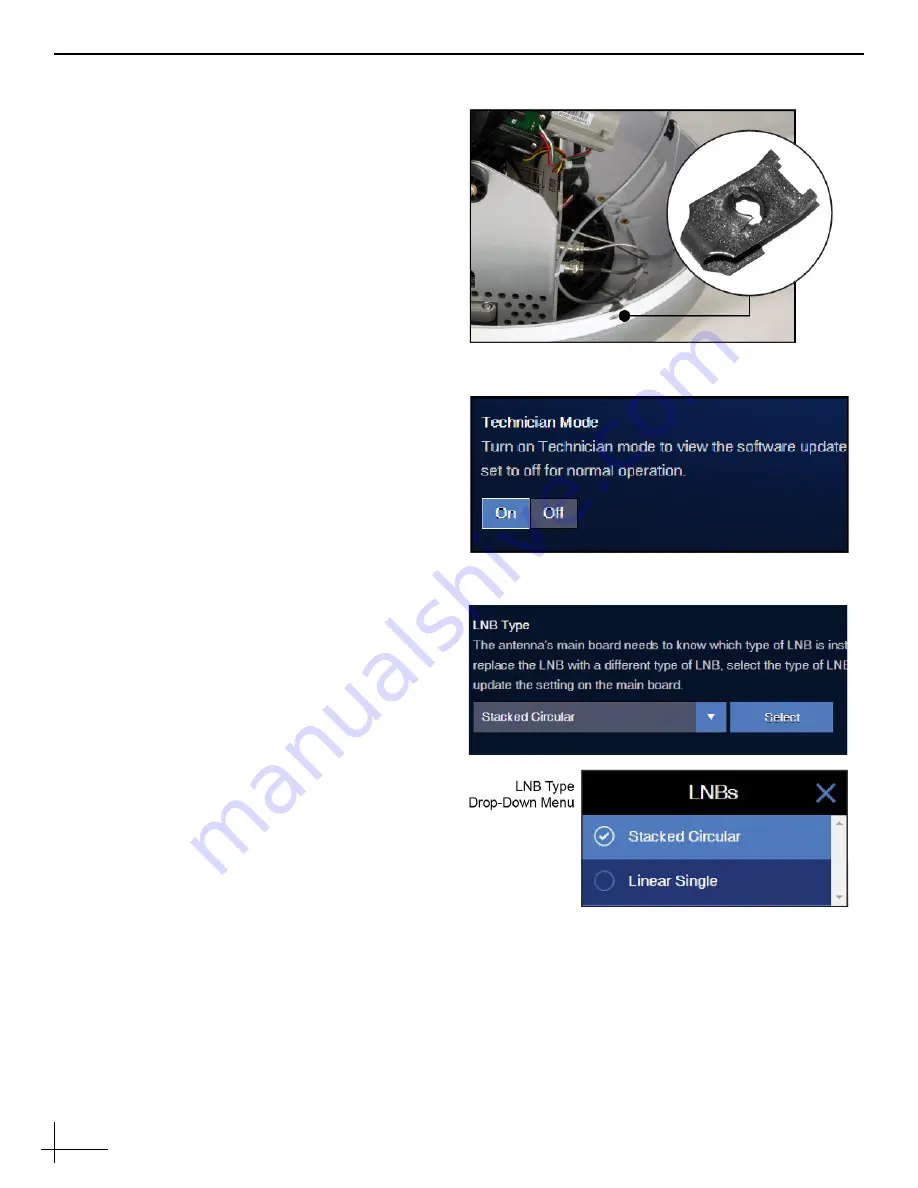
Inspect the four clip-on nuts installed in the
baseplate (see Figure 8). If any are damaged or
missing, replace with one of the four new
clip-on nuts (
supplied in kit
).
s.
Reinstall the radome onto the antenna, aligning
the radome labels forward and aft.
t.
Secure the radome with four new #8-32 screws
(7/16" long) (
supplied in the kit
). Then tighten the
screws to 5 in.-lbs of torque.
u.
Hide and protect the radome screws with the
plastic screw caps (
supplied in kit
).
v.
Reconnect power to the TV-Hub.
Step 2 - Update the Software
Connect your computer to the TV-Hub and access
its web interface, then follow the instructions in the
TracVision TV1/RV1 Help to update the system
software to the latest version.
Step 3 - Register the LNB
If a standard circular LNB is installed in the
antenna
, skip to step 4.
Otherwise
, follow the steps below to register the
LNB with the new main board.
a. If your computer is disconnected from the
TV-Hub,
reconnect now to access its web
interface. (Refer to the TracVision system’s
Quick Start Guide for details.)
b.
At the Settings page of the web interface, choose
Advanced Settings
and set
Technician Mode
to
On
.
c.
From the
LNB Type
drop-down menu, choose
your currently installed LNB (see
.
Then click
Select
.
d.
The TV-Hub will confirm that you want to
change the LNB type. Click
OK
to confirm the
change.
Figure 8: Clip-On Nut Location (x4)
Figure 9: Technician Mode
Figure 10: LNB Type Drop-Down Menu
Содержание TracVision TV1/RV1
Страница 7: ...7...


