2
b.
Disconnect the power/data cable from the back
of the ACU and unplug the AC power cable
from its power source.
NOTE: Follow all shipboard lockout-tagout procedures,
where applicable.
c.
Using a 7/16" socket/ratchet or nut driver,
unlock the three hex latches securing one of the
service hatches to the baseplate (see Figure 2).
Open the hatch.
NOTE: If you are unable to work through the hatch, you
may remove the radome instead. If possible, open the
second hatch as well to allow in more light. Use a
headband light if needed.
d.
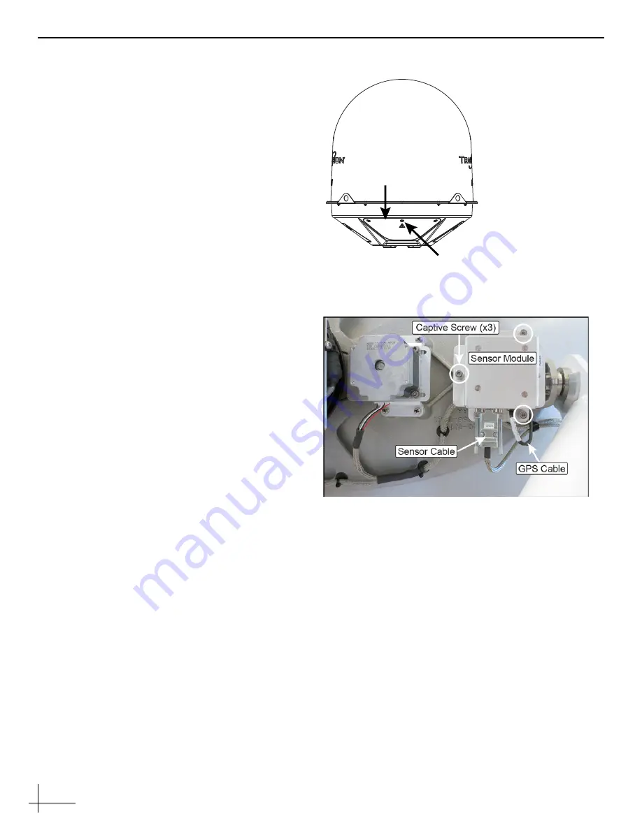
Disconnect the two cables from the sensor
module (see Figure 3) as follows:
d1. Disconnect the GPS cable.
d2. Using a flat-head jeweler’s screwdriver,
loosen the Sensor cable connector’s DB9
retaining screws first to avoid breaking the
screws. Then fully disconnect the cable.
e.
Using a #2 Phillips screwdriver, loosen the three
captive screws securing the sensor module to
the frame.
f.
Remove the faulty sensor module.
Step 2 - Install the Replacement Sensor Module
Follow the steps below to secure the new sensor
module, reconnect the cables, close the hatch, and
apply power.
a.
Secure the replacement sensor module to the
frame and tighten the captive screws to
21 in.-lbs.
b.
Reconnect the two cables to the sensor module
at the locations shown in Figure 3.
When reconnecting the DB9 connector (the
Sensor Cable), tighten the retaining screws to
5 in.-lbs of torque. Do not overtighten –
these
screws break easily.
c.
Inspect the inside of the antenna to make sure
you have not left any tools or debris inside.
Figure 2: Service Hatches
Service
Hatch (x2)
1/4-turn Hex
Latch (x6)
Figure 3: Sensor Module Screws and Cables


