background image

5

Minimize Satellite Blockage

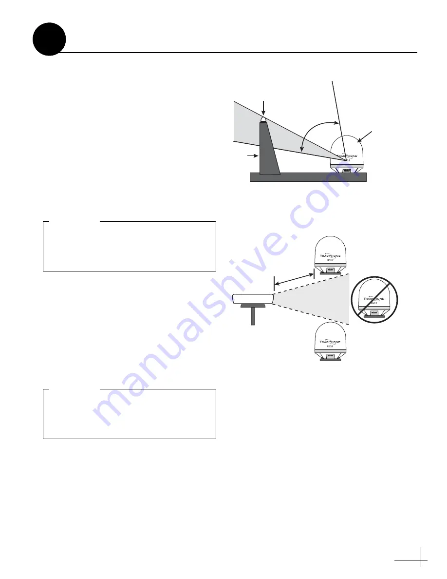
The antenna requires a clear view of the sky to 
transmit and receive satellite signals (see 
Figure 3). The fewer obstructions, the better the 
system will perform.

Avoid RF Interference

Although many variables determine the exact 

distance required between the antenna and 

radar/high-power radio transmitters, including 

transmitter beam properties and the reflective 

properties of nearby surfaces, consider the 

following general guidelines when selecting a 

safe antenna location:

• Mount the antenna as far away as possible 

from the radar and high-power radio 

transmitters.

• Do not mount the antenna at the same level 

as the radar. Most radar transmitters emit RF 

energy within an elevation range of -15° to 

+15° (see Figure 4). Therefore, mount the 

antenna outside this elevation range and at 

least 10 ft (3 m) away from the transmitter. 

Figure 3:  Blockage from Obstruction

Blocked!

Antenn

a

M

a

st

Look Angle

Vessel Pl

a

tform

7.5° to 75°

RF emissions from radars and high-power 

radio transmitters may damage the antenna 

or impair its performance if it’s improperly 

positioned within the beam path.

IMPORTANT!

Figure 4:  Avoiding RF Interference

+15°

-15°

Potenti

a

l RF

Interference

10 ft (3 m)

Minim

um

R

a

d

a

r

Never place the antenna in the beam path of 

the radar regardless of distance. Radar energy 

may damage the antenna or impair its 

performance.

IMPORTANT!

Continued 

Plan the Antenna Installation

2

Содержание TracPhone V3IP

Страница 1: ...KVH Industries Inc Installation Guide TracPhone V3IP in 24 60cm Dome to match TracVision HD7 or M7 tapered baseplate variant ...

Страница 2: ...rvice Technical Support 1 Inspect Parts and Get Tools 3 2 Plan the Antenna Installation 4 3 Plan the ICM Installation 6 4 Prepare the ICM 7 5 Mount the ICM 8 6 Prepare the Antenna Site 9 7 Remove the Shipping Restraints 10 8 Prepare the Antenna Cables 11 9 Wire the Antenna 13 10 Mount the Antenna 14 11 Wire the ICM 15 12 Connect Power 18 13 Turn On the System 20 14 Update the System Software 21 15...

Страница 3: ...VH Technical Support prior to conducting any repairs or modifications to the equipment WARNING Risk of Explosion Do not operate the ICM or any other electrical device in an environment where flammable gases vapors or dusts are present In addition do not operate the ICM in an environment with a temperature outside its 5º F to 131º F 15º C to 55º C temperature range WARNING Risk of Electric Shock Fa...

Страница 4: ...between 34 and 40 ft lbs Light hammer and center punch Adhesive tape Silicone sealant self vulcanizing tape or equivalent Eye protection Shop towels Voltmeter Utility knife Flush cutters Wire stripper terminal crimper File Two 75 RF coax cables F connectors and associated termination tools see page 11 Figure 1 System Components Radome Antenna Baseplate Integrated CommBox Modem ICM Always lift the ...

Страница 5: ... the antenna near any magnetic compasses or other onboard antennas to prevent potential interference Prevent RF Radiation Exposure Select a location that is well above any areas accessible to passengers and crew to reduce the risk of RF radiation exposure See page 1 for an illustration of the hazard area If mounting the antenna near an accessible area is unavoidable you may configure one or two no...

Страница 6: ...o not mount the antenna at the same level as the radar Most radar transmitters emit RF energy within an elevation range of 15 to 15 see Figure 4 Therefore mount the antenna outside this elevation range and at least 10 ft 3 m away from the transmitter Figure 3 Blockage from Obstruction Blocked Antenna Mast Look Angle Vessel Platform 7 5 to 75 RF emissions from radars and high power radio transmitte...

Страница 7: ...he ICM must be located within 100 ft 30 m of the antenna However you can order a 150 ft 45 m cable if a longer cable run is necessary KVH part no 32 1031 0150 Be sure the location provides adequate Wi Fi reception Do not install it in an area surrounded by metal or near any electrical devices that emit RF noise Side View Front View 19 00 48 26 cm 16 75 42 55 cm 3 49 8 85 cm 18 31 46 51 cm 2 25 5 7...

Страница 8: ...ta cable from the A1 jack to the A2 jack b Connect the straight through Ethernet cable from the B1 jack to the B2 jack c Connect the BUC power cable from the C1 jack to the C2 jack Attach the Wi Fi Antennas Connect the two supplied Wi Fi antennas to the rear panel of the ICM see Figure 6 ICM A2 A1 B2 B1 C2 C1 Wi Fi Antenna x2 Figure 6 Jumper Cables Wiring and Wi Fi Antennas Prepare the ICM 4 ...

Страница 9: ...he ICM to a horizontal surface a Remove the six 6 32 screws and washers securing the two rack mount brackets to the front of the ICM see Figure 9 Remove the brackets b Attach the supplied strain relief bracket to the back of the ICM and attach the supplied L mounting brackets to the sides of the ICM using six supplied 6 32 screws and washers see Figure 10 c Mount the ICM to the vessel using fasten...

Страница 10: ...ng surface d Cut out the 3 75 95 mm cable access hole in the location you marked in Step b Smooth the edges of the hole to protect the cables You may also apply anti chafe material around the cables to prevent abrasion e Clean and dry the antenna mounting surface f Peel off the paper backing from the supplied foam seal to expose the adhesive Then press the foam seal down firmly onto the mounting s...

Страница 11: ...from falling overboard b Remove the four 1 2 13 bolts and washers securing the antenna to the shipping pallet see Figure 13 c Remove the two tagged 10 32 shipping restraint screws see Figure 13 Save the restraints for future use d Transport the antenna to the mounting location 10 32 Screw x6 Figure 12 Removing the Radome 1 2 13 Bolt x4 10 32 Screw x2 Washer x4 Figure 13 Shipping Restraints and Bol...

Страница 12: ...0 ft 31 45 m Cable Run Cable LMR 600 75 KVH part no 32 0945 0150 Loss 0 04 dB ft 0 13 dB m Connector Times Microwave EZ 600 FMH 75 Tools Times Microwave TK 600EZ KVH part no 72 0375 75 Strip Lengths 0 25 6 35 mm 0 5 12 7 mm 0 064 1 63 mm dia 0 170 4 32 mm 0 340 8 64 mm 0 065 1 65 mm dia 0 790 20 07 mm 0 250 6 35 mm 0 375 9 53 mm 0 108 2 74 mm dia 0 870 22 10 mm RF cables must be rated for 75 not 5...

Страница 13: ...er data cable and the right angle connector ends of the RF cables at the antenna location NOTE An optional 150 ft 45 m power data cable is available from KVH KVH part no 32 1031 0150 b Route the opposite ends of the power data and RF cables belowdecks through the 3 75 95 mm cable access hole Leave an adequate service loop at least 14 35 cm of slack in the cables at the antenna location c Route the...

Страница 14: ... g Repeat steps d g to connect the TX pigtail cable to the antenna s MTx jack h Wipe off any excess grease from the cables i Use a 15 tie wrap supplied in kit to secure the RF pigtail cables to the connector plate to reduce strain j Seal all above deck RF cable connections with silicone sealant or equivalent k Connect the power data cable to the Power Data jack on the bottom of the antenna see Fig...

Страница 15: ...H recommends that you tighten the bolts to between 34 and 40 ft lbs 46 1 and 54 2 N m of torque d Reinstall the radome onto the baseplate Secure in place with the six 10 32 screws you removed earlier see Figure 12 on page 10 e Install a protective plastic screw cap supplied in the kit over each radome screw CAUTION Be sure to observe the safe handling instructions in the Material Safety Data Sheet...

Страница 16: ... on the cable Secure the clamp in place with the two screws e Carefully fit all of the power data cable s wires within the base of the shroud f Snap the shroud s cover onto the base Be sure not to pinch any wires between the cover and the base g Plug the terminal strip connector into the rear panel of the ICM Figure 21 Antenna Power Data Wiring Antenna Terminal Strip Connector 1 2 11 10 9 8 7 6 12...

Страница 17: ...not accept messages that conform to the NMEA 2000 standard b Make sure the data message s includes the checksum identifiable by a xx field at the end of the data sentence e g HEHDT 123 4 T 1F Do not exceed a 10 Hz input rate c Connect the NMEA 0183 talker or NMEA data multiplexer to the supplied 2 position terminal strip connector as shown in Figure 24 d Plug the terminal strip connector into the ...

Страница 18: ... to 20 in lbs If you are using LMR 600 75 cables do not connect them directly to the ICM Connect the supplied 1 ft 30 cm pigtail cables between the RF cables and the ICM Be sure to use the white pigtail cable labeled TX ONLY at the ICM s TxRF jack IMPORTANT Figure 25 Antenna RF Transmit and Receive Wiring Tx Pigtail White TX ONLY Rx Pigtail Black ICM TxRF RxRF Antenna Pigtails Pigtails if necessar...

Страница 19: ...ge current is unacceptable KVH recommends that you install a suitable isolation transformer to supply single phase power to the antenna system and run a ground wire from the transformer to ship s ground In addition since ground fault protection devices cannot detect faults behind a transformer you will also need to install a ground fault monitoring device between the isolation transformer and the ...

Страница 20: ...rruptible power supply UPS to avoid service interruptions during power outages and transitions to from shore power WARNING Failure to ground the TracPhone system properly to ship s ground will cause an unsafe floating ground condition risking damage to the antenna and electric shock potentially resulting in DEATH In a floating ground condition the difference between the equipment s chassis ground ...

Страница 21: ...ure 31 h Open a web browser on your PC and enter the following address http minivsat kvh i Verify that the web interface appears in your browser If it doesn t enter the ICM s IP address you can find this address on the LCD go to Settings Network Settings IP Assignments and make sure your PC is configured for DHCP addressing see page 39 Power Button ICM Figure 29 Power Button Powering down rebootin...

Страница 22: ...e software using the TracPhone V3 IP web interface However you can also update the software using the mini VSAT iPhone iPod Touch app a USB drive or if the system is activated via the antenna s Internet connection airtime charges may apply Details are available in the Help a Click Choose File b At the Login window enter the default password password c Click Browse and navigate to the file you save...

Страница 23: ...ayed on the home page and in all support communications Follow these steps to enter the correct vessel name a At the TracPhone V3 IP web interface click the Settings tab Then click Account b In Vessel Name click Edit c Enter the vessel name see Figure 35 Then click Save Settings Assign the Phone Line Name The phone line name is displayed on the home page and in all support communications Follow th...

Страница 24: ...be pointing toward the bow see Figure 38 NOTE Each no transmit zone must span at least 5 Therefore be sure to set the beginning and ending azimuths at least 5º apart b At the TracPhone V3 IP web interface click the Settings tab Then click No Transmit Zones c Click Edit d Click Enforce Zones see Figure 39 e Enter the azimuth range for Zone 1 f Enter the azimuth range for Zone 2 if required g Click ...

Страница 25: ...acPhone V3 IP web interface click the Settings tab Then click Tracking Avoidance Zones d Click Edit e Enter the azimuth and elevation ranges for Zone 1 Then select the Enabled check box see Figure 40 NOTE Although you may enter an elevation as low as 25º and as high as 90º the antenna can only receive signals within its 7 5º to 75º operating range f Set up any additional zones by selecting a zone ...

Страница 26: ...g good communications between the TracPhone system and the land based hub see Figure 42 d Turn on all other electronic equipment above deck within the proximity of the antenna Verify that the system continues to operate without any degradation in performance e Fill out the installation checklist provided in the Customer Welcome Kit and return it to KVH Refer to the instructions on the form Figure ...

Страница 27: ... Configuration drop down menu Then click Save see Figure 44 and Figure 45 d At the confirmation message click Save e Follow the additional instructions on the following pages for your chosen configuration Standard Go to page 27 Static IP Go to page 28 Crew Go to page 29 Dual Dome Go to page 30 Figure 43 ICM Ethernet Ports and Wireless Access Point User Ethernet ICM 1 2 3 4 Wi Fi Figure 44 Selectin...

Страница 28: ...cess c Make sure all computers are configured for DHCP addressing see page 39 Devices connected to the ICM via Ethernet cables or Wi Fi will receive IP addresses from the ICM via DHCP see Figure 47 The ICM serves as a router NOTE By default the ICM has a gateway of 192 168 5 1 and assigns IP addresses in the 192 168 5 100 200 range If this configuration conflicts with an existing onboard network y...

Страница 29: ...gure the device s TCP IP properties according to the instructions KVH will provide in an email upon fulfilling the static IP request d Connect all other non static IP computers and or network devices to User Ethernet ports 1 3 and Wi Fi as required These ports and the built in WAP provide direct Internet access without a user login Follow the steps in Standard Configuration on page 27 Figure 48 St...

Страница 30: ...hese additional steps to configure the network a Connect the Crew computers and or network devices to the User Ethernet ports on the ICM that are designated Crew LAN These ports require a user login Follow the steps in Standard Configuration on page 27 b Connect the Operations computers and or network devices to the User Ethernet ports on the ICM that are designated Ops LAN if any These ports prov...

Страница 31: ...er 192 168 0 10 and not minivsat kvh to access the secondary system s web interface d Connect your laptop to the primary system At the web interface select the Dual Dome Primary network configuration e Connect an Ethernet cable from any User Ethernet port on the secondary system s ICM to User Ethernet port 4 on the primary system s ICM see Figure 53 f Connect the customer s computers and or networ...

Страница 32: ...e name for the vessel network Protocol Select either 802 11b or 802 11g Security Select either security type WPA2 or WEP 128 bit Password Passphrase If you selected WPA2 enter a password between 8 20 characters If you selected WEP enter a passphrase must be 13 characters Channel Keep the default or select any channel for wireless communications d At the confirmation message click Save Figure 54 Wi...

Страница 33: ... about installing and configuring the Media Server Optional CommBox Software CommBox software extends the system s network capabilities Two options are available Standard Bundle Provides least cost routing onboard firewall web caching web image compression ad removal and URL and content filtering Enterprise Bundle Adds automated file transfers differential synchronization mail relay server web mai...

Страница 34: ...ce Line 1 jack is enabled for use Connecting Optional Accessories KVH offers optional accessories that extend the capabilities of the TracPhone system For example the UCH 250 Fax Server KVH part no 19 0520 is an enterprise grade fax solution that provides a dedicated fax line using a fully managed store and forward fax service Refer to the instructions provided with the accessory to connect it to ...

Страница 35: ...ees buildings and bridges see Figure 60 Dirt buildup on the radome can also affect communications The vessel must be located within the coverage area of the satellite see www kvh com minivsatmap The system must be activated for mini VSAT Broadband service see www kvh com mvbservice Data usage and overage alerts via email and text message as well as user logins and their associated data allocations...

Страница 36: ... end of the cable using a pair of needle nose pliers see Figure 63 Also make sure the center conductor is centered within the cable 3 Place the heat shrink sleeve and metal ferrule onto the cable see Figure 64 4 Insert the end of the cable into the 1 end of the ST 400EZ stripping tool see Figure 65 Then rotate the tool clockwise around the cable until the tool turns easily The end of the cable sho...

Страница 37: ...the tool turns easily This removes the cable jacket from the end of the cable exposing the braid and dielectric see Figure 68 7 Using the DBT 02 tool deburr and chamfer the center conductor see Figure 69 Avoid nicking the aluminum tape covering the dielectric Figure 66 Removing Plastic Residue Figure 67 Stripping the Cable Jacket Figure 68 Cable Stripped Exposing Dielectric Figure 69 Deburring the...

Страница 38: ...e braid until it is flush against the connector shoulder see Figure 73 Figure 70 Flaring the Braid Figure 71 Pushing On the Connector A common installation failure occurs when the connector is not seated properly onto the cable In these cases the cable s center conductor does not fully engage the electrical contacts inside the connector To ensure full engagement make certain that there is no gap b...

Страница 39: ...ace see Figure 75 When you are done the heat shrink should extend from the rear of the connector to the cable jacket This forms a weather tight seal 15 Using a multimeter or similar device check the continuity of the cable 16 Ensure the center conductor pin measures between 0 20 and 0 28 5 7 mm in length to ensure proper engagement with the mating connector see Figure 76 Figure 74 Crimping the Fer...

Страница 40: ...ttings Network Internet Ethernet Network and Sharing Center 3 In Network and Sharing Center click the Ethernet link for the Ethernet connection you are using 4 In the Ethernet Status dialog box click Properties If this screen doesn t appear just skip to Step 5 5 In the Ethernet Properties dialog box on the Networking tab select Internet Protocol Version 4 and then click Properties 6 In the Interne...

Страница 41: ... Status dialog box click Properties If this screen doesn t appear just skip to Step 5 5 In the Ethernet Properties dialog box on the Networking tab select Internet Protocol Version 4 and then click Properties 6 In the Internet Protocol Properties dialog box select Obtain an IP address automatically and Obtain DNS server address automatically see Figure 78 Then click OK 7 In the Ethernet Properties...

Страница 42: ...ing 4 In the Local Area Connection Status dialog box click Properties If this screen doesn t appear just skip to Step 5 5 In the Local Area Connection Properties dialog box click the Networking tab select Internet Protocol Version 4 and then click Properties 6 In the Internet Protocol Properties dialog box select Obtain an IP address automatically and Obtain DNS server address automatically see Fi...

Страница 43: ...his screen doesn t appear just skip to Step 5 5 In the Local Area Connection Properties dialog box click the General tab select Internet Protocol TCP IP and then click Properties 6 In the Internet Protocol TCP IP Properties dialog box click the General tab Then select Obtain an IP address automatically and Obtain DNS server address automatically see Figure 80 Then click OK 7 In the Local Area Conn...

Страница 44: ...ces click Network 3 In the Network dialog box select Ethernet then set the following Location Automatic Configure IPv4 Using DHCP 4 Click Apply 5 Restart the computer Figure 81 Macintosh OS X Network Preferences Continued Configuring Computers for DHCP B Appendix ...

Страница 45: ... White White Blue Brown White Terminal Strip Connector Power Data TxRF RxRF Red Black White Gray Gray White Ground Six unused wires are reserved for future use N C Not Connected A2 A1 B2 B1 C2 C1 1 2 11 10 9 8 7 6 12 5 4 3 13 14 15 16 To Antenna Vessel PC Vessel Phone Voice Line 1 User Ethernet 1 NMEA 0183 Talker s optional customer supplied A B 1 2 NMEA Ship s Heading and or Position Appendix ...

Страница 46: ...54 0959 Rev A ...

Страница 47: ... 847 3327 Fax 1 401 849 0045 E mail info kvh com KVH Industries A S EMEA Headquarters Kokkedal Denmark Tel 45 45 160 180 Fax 45 45 160 181 E mail info emea kvh com KVH Industries Pte Ltd Asia Pacific Headquarters Singapore Tel 65 6513 0290 Fax 65 6472 3469 E mail info apac kvh com ...

Отзывы: