


36
Maintenance and Troubleshooting
36
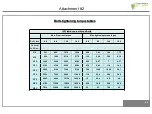
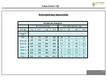
Replacing hydraulic cylinder
- Loosen the hydraulic nipples, the hoses, and the
copper washers
Hydraulic hoses
Copper washer
Hydraulic nipple
Hexagonal head
screw
Washer
Self locking nut
- Loosen the hexagonal head screw and the self locking
nut, remove them and the washer
Offset hydraulic
cylinder
Содержание FHS 155
Страница 5: ...5 General data and equipment Landmark Orientation 5 ...
Страница 11: ...11 General data and equipment Optional equipment glossary 11 Rake tines rear cover Second Counterknife Kit ...
Страница 38: ...38 Maintenance and Troubleshooting 38 Adjusting rake tines ...
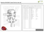
Страница 51: ...51 Gearbox MAG636 Comer Service manual 51 ...
Страница 52: ...52 1 Disassembly 52 ...
Страница 53: ...53 2 Assembly B 53 ...
Страница 54: ...54 3 Technical specifications 54 ...