Kval ON-HD Скачать руководство пользователя страница 40

Universal Controls

KVAL ON-HD Operation Manual

2-10

Universal Controls

These controls are located on every screen

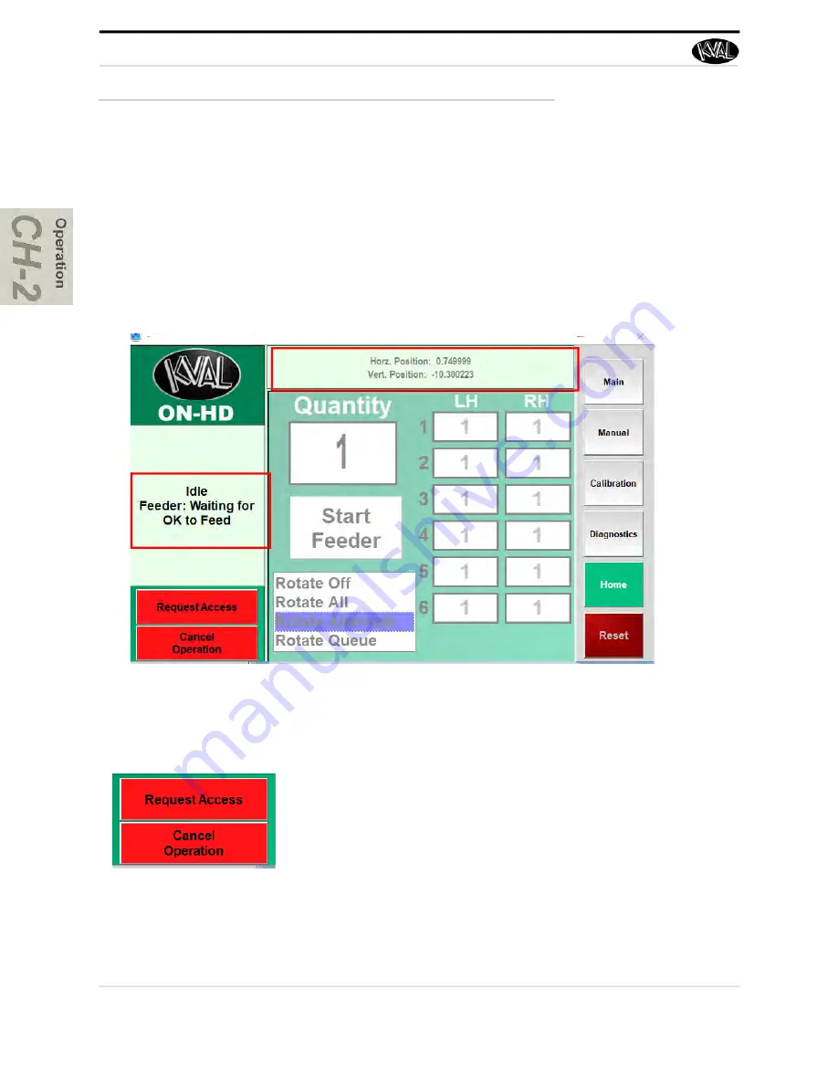
About Machine Status Feedback 

At the right-hand side of the screen, feedback from the machine is displayed. The top window dis

-

plays servo locations. The machines are constantly polled, feeding back their state of operation. 

This feedback is a great tool to instantly view the status of each machine.This information can be 

used to troubleshoot any issues that may occur. 

Request Access and Cancel Operation

Machine Feedback

Machine Feedback

Request Access: P

ress to request access to the machine. 

This software button simulates the same action as pushing the 

request access button at the Feeder entrance. 

See “ON-HD Lift 

Main Control” on page 2-6.

Cancel Operation 

I Press to stop the operation of a door 

being lifted. If pushed during the lift sequence, the gantry will 

move the door back to the stack. If pushed before the door is 

picked up, the gantry will go into the park position N

ote

: This 

operation must be utilized before the door is placed on the 

table.

Содержание ON-HD

Страница 1: ...Innovation Quality Honesty Operation Manual Published February 17 2022 ON HD Lift ON HD Operation Manual ...

Страница 2: ...ered trademark of Microsoft Corporation All other products are trademarks or registered trademarks of their respective holders all rights reserved Reference to these products is not intended to imply affiliation with or sponsorship of Kval Incorporated Contacting KVAL Customer Service For further information about this manual or other Kval Incorpo rated products contact the Customer Support Depart...

Страница 3: ...erience with our product that is the manual the machinery the software etc What was easy or difficult to use or to learn If you could change something about the design what would it be Please email your comments and suggestions for improve ment to userexperience kvalinc com NOTE This is not a customer support email link For that please refer to the Customer Service contact information above Thank ...

Страница 4: ...KVAL ON HD Operation Manual ...

Страница 5: ...e 1 11 Pre Steps Before Lockout Tagout 1 11 Lockout Tagout Power 1 11 Lockout Tagout Air Supply 1 12 Start Maintenance 1 12 Post Maintenance Steps 1 12 Zero Energy to Start Up 1 13 Getting Help from Kval 1 15 Kval Return and Warranty Policy 1 16 Send the Item 1 16 Acceptance of Return 1 16 Refund Turnaround Time 1 16 Kval Errors 1 16 Customer Errors 1 17 Shipper Errors 1 17 Warranty Replacement Pa...

Страница 6: ...ump Reset and Home Buttons 2 11 About the ON HD Lift Main Screen 2 12 About the ON HD Lift Main Control Screen 2 12 About the ON HD Lift Manual Operation Screen 2 14 About the ON HD Lift Manual Control Screen 2 14 About the ON HD Lift Calibration Screen 2 16 The Calibration Screen 2 16 Entering Calibration Offsets 2 17 About the ON HD Lift Diagnostic Screen 2 20 About the ON HD Lift Manual Control...

Страница 7: ...ntrol 3 7 Staging Area Controls 3 9 About the Safety Curtain 3 10 If the Field is Broken 3 10 To Resume Normal Operation after an Field is Broken 3 10 Location of Safety Curtain on the ON HD Lift 3 11 About the Electrical Panels 3 12 The Light Tower 3 13 About the Nodes 3 13 Graphical Sample of Node Connections and Power Distribution 3 14 ...

Страница 8: ...KVAL ON HD Lift Manual Table of Contents ...

Страница 9: ...First IMPORTANT safety information is described in this section page 1 6 Lockout Tagout Guidelines Procedures describing Lockout Tagout page 1 10 Zero Energy to Start Up Procedure to power up your machine for the first time page 1 13 Getting Help from KVAL This section describes the method to contact the KVAL service center for help The section includes how to get information from the specificatio...

Страница 10: ... ON HD Lift is a vacuum lifting system that is combined with AC servo motors for vertical and horizontal movement which ensures accurate and smooth positioning The power conveyor tables feature pop up jump belt systems to properly align doors against edge guides for in feed and re stacking ...

Страница 11: ...n 1 Introduction Descriptions of Machine Line and Safety Information 2 Operation Interface Descriptions of how to power machine line and operator inter face user screens 3 Tour A Tour of the machine Chapter Title Description 1 Introduction Descriptions of Machine Line and Safety Information 2 IT System Descriptions of the PLC 4 Maintenance Maintenance steps for the machine line 5 Troubleshooting T...

Страница 12: ...ed or illegible There are three types of warning labels or decals DANGER means if the danger is not avoided it will cause death or serious injury WARNING means if the warning is not heeded it can cause death or serious injury CAUTION means if the precaution is not taken it may cause minor or moderate injury Safety Guidelines In addition to the caution and warning labels affixed to this machine fol...

Страница 13: ...Safety First KVAL ON HD Operation Manual 1 5 ...

Страница 14: ...ed or illegible There are three types of warning labels or decals DANGER means if the danger is not avoided it will cause death or serious injury WARNING means if the warning is not heeded it can cause death or serious injury CAUTION means if the precaution is not taken it may cause minor or moderate injury Safety Guidelines In addition to the caution and warning labels affixed to this machine fol...

Страница 15: ...n Never perform any maintenance unless machine is at zero state Never clean the machine while it is running Never walk away from the machine while it is running When the Machine is ON The compressed air system connected to this machine should have a three way air valve for shut off and pressure relief All cylinders on machine are under high pressure and can be very dangerous when activated Before ...

Страница 16: ...ed at different locations Before performing any repairs or mainte nance lockout and tagout must be installed at all locations All maintenance and repairs to electrical circuitry should only be per formed by a qualified electrician Still has power in OFF position Electrical Prior to performing any maintenance repairs cleaning or when clearing jammed debris you must disconnect tag out or lock out th...

Страница 17: ... If you believe any part or operation of this machine is in violation of any health or safety regulation STOP pro duction It is your responsibility to immediately protect your employees against any such hazard Additional detailed safety guidelines are included in the operating instructions of this manual KVAL will be pleased to review with you any questions you may have regarding the safe operatio...

Страница 18: ...and tag on each disconnect Only each operator may remove their own lock and tag Important When many people are all working on the same machine you will need a multiple lockout device such as the one shown here Follow the P R O P E R lockout rule of thumb P Process shutdown R Recognize energy type electrical pneumatic mechanical etc O OFF Shut off all power sources and isolating devices P Place loc...

Страница 19: ...supply and pressure spring tension weight shifts etc 2 Inform all affected personnel of the eminent shutdown and the duration of the shutdown 3 Obtain locks keys and tags from your employer s lockout center 4 Turn off machine See Chapter 2 for power down and power up procedures 5 Turn the disconnect switches on ALL electrical and frequency panels to the OFF position Then push the red tab to pop it...

Страница 20: ...re completely removed and that all guards and safety devices are installed 10 Before removing the locks and tags the person who attached them shall inspect the equipment to ensure that the machine will not be put in an unsafe condition when re energized 11 The lock and tag can now be removed only by the person s who placed them and the machine can be re energized 12 The tags must be destroyed and ...

Страница 21: ... when energy is restored Remove Locks Each operator must remove his or her own lock and tag This will ensure that all oper ators are in a safe place when the equipment is started Perform Visual Checks If the equipment is too large to see all around it station personnel around the area and sound the personnel alarm before starting the equipment If your operation is more complex your company s compr...

Страница 22: ...key to your lock Proper lockout tagout can save lives limbs and money Help make your work environment safe for you and your fellow workers Be sure to follow the P R O P E R lockout tagout procedures and that those around you do also Close the Cage Gate Verify all cage gates are securely closed Ensure all safety protocols are in effect ...

Страница 23: ...cord the serial number 3 phase volts electrical print number and air print number 2 Contact our customer support team In the U S and Canada call 800 553 5825 or fax 707 762 0485 Outside the U S and Canada call 707 762 7367 or fax 707 762 0485 Email address is service Kvalinc com Hours 6 00 AM to 4 00 PM Pacific Standard Time Monday through Thursday 6 30 AM to 1 30 PM Pacific Standard Time Friday A...

Страница 24: ...RMA _______________ Send the Item Return the item to this address Kval Inc RMA ______ Kval Parts 825 Petaluma Blvd South Petaluma CA 94952 USA Acceptance of Return We can only accept items for a return if they are still in their original packaging and in undam aged resalable condition Returns are accepted within 45 days of purchase and with an RMA number issued by Kval Inc Returns after 45 days of...

Страница 25: ... more than one 1 year after delivery will the product be covered under Warranty The repair replacement or payment in the manner described above shall be the exclusive remedy of Buyer for breach of Kval s warranty or for claims based upon failure of or defect in the products regardless of when the failure or defect arises and whether a claim however described is based upon contract warranty indemni...

Страница 26: ... 2 At the KVAL website select the Support tab Follow the instruc tions on the Support web page 3 Click the Download button to download the application that allows the KVAL technician to have access to the operator sta tion 4 After the download is com pleted double click the program icon Note Web browsers have different methods of downloading programs Below are samples of i e Explorer and Google we...

Страница 27: ...ogram is ready to allow technicians to access machine computer Your Name Field Enter your name The KVAL tech nician will use this field to identify this machine Description Enter machine Serial number and issue Indicator Green indicates there is a good connec tion to the service center If red there could be an issue with a LAN connection Check the connections in the plant 7 After the KVAL Support ...

Страница 28: ...How to Download the Service Application KVAL ON HD Operation Manual 1 20 Page Intentionally Left Blank ...

Страница 29: ...ow my company s safety procedures I have read and understand these guidelines Machine Safety Concerns I have been given a tour of the machine and understand all the safety labels E Stops and the actions to take in case of an emergency I will make sure all guards are in place before operation I will turn off the compressed air before loading hardware staples screws etc I will turn off the electrica...

Страница 30: ...Safety Sign Off Sheet KVAL ON HD Operation Manual 1 22 ...

Страница 31: ...rate the machine and process a door Chapter 2 at a Glance Section Name Summary Page About the Machine Line A Summary of the entire machine line page 2 2 Initial Power Operations Description of powering up the line from the off state Includes Power down description Six Light Panel and homing the machine line page 2 3 Machine Start Summary A quick summary of running a door through the machine page 2...

Страница 32: ...orient doors correctly in the stack before processing In this example the ON HD Lift operates as a as a feeder to feed doors into the machine line Stacker ON HD Lift are also available A feeder takes a door from a stack and inputs it into a door machine for processing A stacker is located at the end process and takes the door from the door machine and stacks them to get ready for the next step in ...

Страница 33: ... and safety gates are closed Note A pop up is displayed on the user screen if an E Stop is pressed The pop up will indicate which E Stop has been activated Don t Forget Air ON Closed Gates and E Stops Turn ON E Box Disconnect 3 Make sure the electrical disconnect each electrical cabinet is turned to the ON position 4 Switch the green Computer switch to the ON positions It will light up 5 Push the ...

Страница 34: ...ge resulting from power surges from electrical storms The Machine Line must go through a homing routine before any operations are performed The homing routine sets a zero reference from which each machine measures its movement and cutting process If power is lost or any machine is reset the homing routine must be performed again Each machine has a Home button on it s associated Main Control Screen...

Страница 35: ... To Resume Normal Operation after an E Stop If an E Stop is activated use the following procedure to recover after the cause of the emergency stop is resolved 1 De activate the E Stop switch by pulling it out 2 Push the Start Machine button on the operator s station 3 Home the machine Other Safety Controls Other safety controls can include Gate Latches Sensors are located on the gates surrounding ...

Страница 36: ...ntrols Operator Interface See Summary of the Interface on page 2 9 Machine controls See below Staging Area Controls See Staging Area Controls on page 2 7 Computer Energize and De Energize the machine Start Machine Wake s up the computer similar to a boot up Start Sequence Start the process to lift and transport the doors Reset Light Curtain Also located at the entrance of the Lift See Staging Area...

Страница 37: ...area and PULL OUT the Request Access Button 4 Press the Reset Light Curtain Button to continue with the process The Request Access Button will turn to a steady blue color Emergency Stop Press the Emergency button to stop machine Will maintain clamp and lift To restart machine see To Resume Normal Operation after an E Stop on page 2 5 Pause Resume Lift Press to pause lift Pull out the button to Res...

Страница 38: ... Reset Light Curtain 9 The Vacuum Carriage moves over the door stack and lifts door Note Door may be rotated 180 at this point 10 The table pops up and door is cen tered 11 Door is placed on the conveyor table When all conditions are met the door is fed into the next machine 12 The ON HD Lift repeats the door pick up and loading process until the Quantity entered is depleted 5 Select Home Button d...

Страница 39: ...utton control of the rotate process control of aces to the machine and quantity of doors to be processed See About the ON HD Lift Main Screen on page 2 12 Manual Servo Control From this screen move the Gantry and Table manually See About the ON HD Lift Manual Operation Screen on page 2 14 Calibration From this screen calibrate the Gantry Lift and Table servos on the machine See About the ON HD Lif...

Страница 40: ... be used to troubleshoot any issues that may occur Request Access and Cancel Operation Machine Feedback Machine Feedback Request Access Press to request access to the machine This software button simulates the same action as pushing the request access button at the Feeder entrance See ON HD Lift Main Control on page 2 6 Cancel Operation I Press to stop the operation of a door being lifted If pushe...

Страница 41: ... will reset the machine to the start position before homing Press Home Machine after Reset Machine Home Machine This button starts the home sequence on the machine which scans to find a physical reference point on the frame When this point is found the position is stored and then used to calculate the location of all moves during the machine process The home sequence must be performed every time t...

Страница 42: ...ain Screen The Main Screen is th boot up screen when at another screen press the button to jump back to the Main Screen From this screen all the basic user interface controls are available to run a door Non Rotation Model For the non rotation model just enter the number of doors to be processed The processing will pause after all the quantity of doors is used up ...

Страница 43: ...t Feeder Press to start the process of machining a door from feed to finish Ensure all machines in the production line are powered up homed and is clear to process Door Quantity Select and enter the number of doors to be processed Note Entering 0 into the Quantity box puts the machine in Full Stack Mode The machine will process the full stack and stop when the last door is finished Important For t...

Страница 44: ...n all the basic user interface controls are available to run a door About Pause Vacuum Sleep and Exit Application Pause Resume Select the Pause button to hold process of the door Select again to Resume from the point where the pause was initiated Vacuum Sleep This but ton puts the vacuum in sleep mode Any door in process of lifting will hold its position Exit Application Press the button to close ...

Страница 45: ...desired button to control the Gantry Take the Gantry up or down Move doors to the roll table or to the stack Clamp or unclamp the door Feeder Table Buttons Press the desired button to control the feed through of the door Feed the door forward or reverse Forward Yo the next machine Reverse back away form the next machine into the feeder Control the crossfeed in the forward or reverse direction Forw...

Страница 46: ...ON HD Lift Manual Control Screen Select the Calibration Button open access to the Gantry Calibration screen Door Stack Calibration screens Feeder screen In this screen you can perform machine calibration of the lock location and lock bore location on the back section change machine timing and speeds and position the jamb shelf on the front section ...

Страница 47: ...oor and adjusting the offset until satisfied with the result 2 Enter the offset positive or negative number in the box next to the Offset button 3 The Base display box keeps a running total of data entered to help keep track of the changes 4 The Combine with Base button merges the off set number to the base to adjust the servo About The Gantry Calibration Select the Gantry Calibration button to ad...

Страница 48: ...k parameters Jump Buttons Select the to go to desired Calibration screens Door Stack 1 Horz This adjusts the location of the gantry of the alignment to the stack Door Stack Low Stack Vert This adjustment adjusts the lowest point of the gantry to the last door This adjust ment is essential if using the Full Stack Mode See About the Main Control Menu on page 2 13 ...

Страница 49: ...19 About The Feeder Calibration Select the Feeder Calibration button to adjust Feeder parameters Jump Buttons Select the to go to desired Calibration screens Feeder Table Horz This adjusts the location of the gantry of the alignment to the Table Table Height Future Option ...

Страница 50: ...ft per forms This screen can help with trouble shooting by associating the error code to machine sections or functions The top line will have the most current routine that is running If the machine issue can not be resolved call KVAL Inc 1 800 553 5825 Have any error code that is displayed ready to give the KVAL representa tive This will aid in troubleshooting and shorten down time The Diagnostic ...

Страница 51: ...lize Red Machine Error Solid General Error 1 Flash EtherCat Device not Ready to Run 2 Flashes VFD Servo or Motor Error 3 Flashes 24 VDC Power Error Yellow External Error Solid General Error 1 Flash 3 Phase Voltage Error 2 Flashes Low Air Error Blue Operator Status Solid Waiting for Operator 1 Flash Reposition Door Green Machine is Operational Safety OFF Clear Safety Project not Running Red Safety ...

Страница 52: ...l from the emitter When the signal is blocked of any field the machine stops To continue machining push the Start button Important The EZ Screen system is aligned at the factory Do not move the emitter or receiver modules This may cause misalignment if the system is mis aligned the machine will not start FIGURE 2 5 Operation of Safety Curtain If the Field is Broken If the field is broken the machi...

Страница 53: ...Manual 2 23 Location of Safety Curtain on the ON HD Lift The ON HD Lift offers the versatility to load and unload doors from the front or sides Safety Cur tains are located on the sides and the front of the ON HD Lift Feeder Loading Safety Curtain ...

Страница 54: ...About the Safety Curtain KVAL ON HD Operation Manual 2 24 ...

Страница 55: ... HD Line page 3 2 Identification of Key Parts of the ON HD Lift A tour of the Machine Description of assemblies on the machine page 3 2 About the Lift Assembly A tour of the Lift Assembly page 3 3 About the Infeed and Outfeed Tables Descriptions of the Infeed and Outfeed Tables page 3 6 About the Safety Curtain What to do if a field is broken and how to resume operation page 3 10 About the Electri...

Страница 56: ...scribes the key parts of the ON HD Lift ON HD Lift Top View FIGURE 3 6 Top View of the ON HD Lift Vacuum Pump Motor Door Lifting Pads Infeed Door Roll Table Light Curtain Front Loading of Doors Light Curtain Front Unload ing of Doors Local Control Motor and Belt Drive Drive over to door and back to Rollers Door Stacking Area Feed Direction ...

Страница 57: ...tifies the main parts on the Carriage assembly Boom Assembly Below are key components of the Boom Assembly FIGURE 3 7 Components on thew Boom Assembly Option Rotate Door Some ON HD Lift have a gear drive to rotate doors Up and Down Servo Motor assembly Drives Grabber to pick up and place door on rollers Vacuum Pads Uses suction to move a door Vacuum Motor Sys tem Provides suc tion to Lifting Pads ...

Страница 58: ...ge Assembly Figure shows both sides of assem bly FIGURE 3 8 Components on the Lift Assembly Vacuum Motor Motor Air Manifold Con trols Pneumatics in Carriage Option Rotation Gear Rotates Door 180o Vacuum Pads Two Pads Horizontal Servo Motor Up and Down Servo Motor Up and Down Brake Horizontal Gear Box Up and Down Gear Box ...

Страница 59: ...About the Lift Assembly KVAL ON HD Operation Manual 3 5 About the Grabber Gripper X2 Vacuum Input Rotate Track Gripper Gauge Gauge ...

Страница 60: ... the door FIGURE 3 9 Locations of the In feed and Outfeed Tables Pop Up Cylinders x4 Elevates rollers to move door to the fence Cross Feed and Feed Motor When cross feed belts pop up this motor moves the door to the fence When cross feed cylin ders re retracted door is fed into table Feed Rollers Moves door into Table Cross Feed Belts X2 Moves door to the fence Bottom View Top View Eye Outfeed Eye...

Страница 61: ...ng area The controls are designed for safety during the operation of the machine The controls can pause the machine to allow safe entry dis able the lift reset the lift and apply emergency stop ON HD Lift Main Control The ON HD Lift controls are located on the Main Control Panel For detailed information about the start up process see Chapter 2 ...

Страница 62: ...ft Press to pause lift Pull out the button to Resume Oper ation The action in process will be paused and maintained Note If enter ing the staging area use the Request Access buttons located on the Staging area frames For details on using the Request Access button see page 3 9 Start Sequence After templates and programs are loaded the doors are in place to process the machines is homed Press the St...

Страница 63: ...ea To Exit the Staging Area 1 After task is completed exit the door staging area and PULL OUT the Request Access Button 2 Press the Reset Light Curtain Button to continue with the pro cess Note These buttons must be used On initial start up of the machine line Emergency Stop Press the Emergency button to stop machine Will maintain clamp and lift To restart machine see To Resume Normal Operation af...

Страница 64: ... from the emitter When the signal is blocked of any field the machine stops To continue machining push the Start button Important The EZ Screen system is aligned at the factory Do not move the emitter or receiver modules This may cause misalignment if the system is mis aligned the machine will not start FIGURE 3 10 Operation of Safety Curtain If the Field is Broken If the field is broken the machi...

Страница 65: ...Manual 3 11 Location of Safety Curtain on the ON HD Lift The ON HD Lift offers the versatility to load and unload doors from the front or sides Safety Cur tains are located on the sides and the front of the ON HD Lift Feeder Loading Safety Curtain ...

Страница 66: ...nel Refer the machine s electrical prints for in depth information The Main Electrical Panel Supplies voltages to the machine Contains the PLC Programmable Logic Controller Contains VFD s Variable Frequency Drives and Servo Drives FIGURE 3 11 Electrical Box for ON HD Lift Relays 24 VDC Supply 24 VDC 110 VAC Light Curtain Terminals Thermal Resistor VFD Feeder Motors Out Feed Cross Feed Vacuum Servo...

Страница 67: ...Light Tower on page 2 25 for more information about the light sequences About the Nodes Nodes are interfaces to the Main Electrical Panel Nodes contain inputs and outputs of PLC and power connections For example door sensors width adjusts and tool interfaces Note The node layout in the figure below is generic For information about the spe cific machine node refer to the machine electronic schemati...

Страница 68: ...aphical Sample of Node Connections and Power Distribution The ON HD frame node is located on the machine boom Power and PLC connections are located in the node boxes FIGURE 3 12 Sample of a Frame Node Node Location Power and PLC Distributed to Points in the Machine ...

Страница 69: ...13 lockout procedure 1 11 M main electrical panel description 3 12 P power lock out procedure 1 11 powering up and down machine 2 3 R remote operation setting up machine for 1 18 reset machine button description user interface 2 10 S safety guidelines 1 4 1 6 Safety Sign Off Sheet Safety Concerns 1 21 six light panel description 2 21 start machine button power up 2 3 2 6 3 8 T tagout procedure 1 1...

Страница 70: ...Index Kval ON HD ...

Страница 71: ......

Страница 72: ...partment Kval Incorporated 825 Petaluma Boulevard South Petaluma CA 94952 Contacting KVAL Phone and Fax In the U S and Canada call 800 553 5825 or fax 707 762 0485 Outside the U S and Canada call 707 762 7367 or fax 707 762 0485 Email service kvalinc com http www kvalinc com ...

Отзывы: