


Touch Screen Troubleshooting
979-2
81
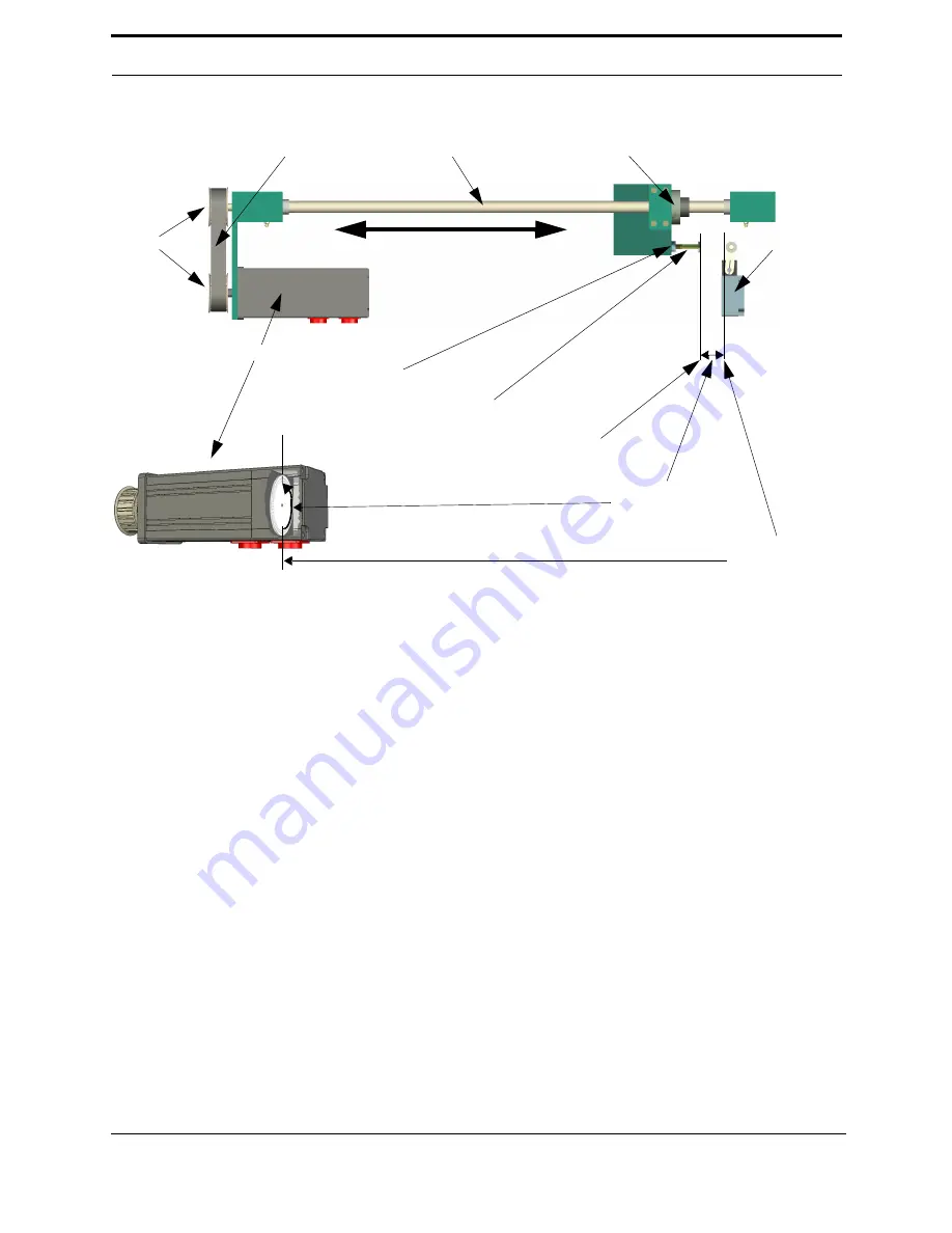
Limit - Switch Timing
General process description:
Note:
Most KVAL machines automate this process, see “979-2 X Axis Limit Switch Timing” on
page 82 for machine specific instructions.
Limit Switch Timing sets the home position of an axis in relation to the Index marker pulse generated
by the CNC motor. Ideally the index marker pulse should be one half a motor rotation away from the
home limit switch activation point. This is accomplished by:
1.
Moving the axis to the home limit activation point
2.
Backing away form the home limit switch until the home limit is deactivated
3.
Rotating the motor until the index marker pulse is generated.
4.
Measuring the amount of motor rotation. If the rotation is between.4 and.6 the homing process is com-
plete.
5.
If the amount of motor rotation is less than.4 or grater than .6 the limit switch activator bolt needs
adjustment. If adjustment is necessary, put wrenches on both the limit switch activator bolt and the
limit switch lock bolt, then loosen the lock bolt. The limit switch activator bolt is now free for adjust-
ment. Adjustment should be made in small increments, best practice being two or three bolt flats at a
time.
• If the motor rotation is less the .4* turn the limit switch activator bolt clockwise, increasing the motor
rotation distance.
• If the motor rotation is grater than .6* turn the limit switch activator bolt counter clockwise, decreas-
ing the motor rotation distance.
6.
Tighten the limit switch lock bolt using the two wrench method mentioned in step 81
*
1 = one full motor rotation.
Index Marker
Pulse
Home Limit
Ball Screw
CNC Motor
Belt
Pulleys
The distance of
motor rotation.
Ball Nut
approximately one half
Axis
Limit Switch
activator Bolt
Home Position
Limit Switch
Lock Bolt
Home Limit Switch
Activation Point
(Must be 5º
Switch
travel)
Note:
The Home Limit Switch and /or Limit Switch Activator Bolt is painted orange on some models.
Содержание 979-2
Страница 1: ...979 2 Innovation Quality Honesty 979 2 Miter Trim Saw System Reference Published 4 24 07 ...
Страница 2: ...979 2 ...
Страница 4: ...b 979 2 ...
Страница 8: ...f 979 2 ...
Страница 10: ...Introduction 2 979 2 ...
Страница 20: ...12 979 2 ...
Страница 21: ...979 2 13 CHAPTER 2 Operation The following chapters explain normal operation of the 979 2 ...
Страница 22: ...Operation 14 979 2 ...
Страница 24: ...16 979 2 ...
Страница 26: ...18 979 2 ...
Страница 36: ...28 979 2 ...
Страница 52: ...Maintenance 44 979 2 Grease Points Main Frame Bottom View Bottom View ...
Страница 53: ...Lubrication Requirements 979 2 45 Fixed Head ...
Страница 54: ...Maintenance 46 979 2 Movable Head Bottom View ...
Страница 56: ...48 979 2 ...
Страница 57: ...Cut Depth Set up 979 2 49 ...
Страница 58: ...50 979 2 ...
Страница 59: ...Cut Depth Set up 979 2 51 ...
Страница 60: ...52 979 2 ...
Страница 64: ...56 979 2 ...
Страница 65: ...979 2 57 CHAPTER 5 Troubleshooting ...
Страница 87: ...Touch Screen Troubleshooting 979 2 79 Technical Support Contact information ...
Страница 92: ...84 979 2 ...
Страница 98: ...90 979 2 ...
Страница 100: ...92 979 2 ...
Страница 102: ...94 979 2 ...


