4
USING THE SYSTEM
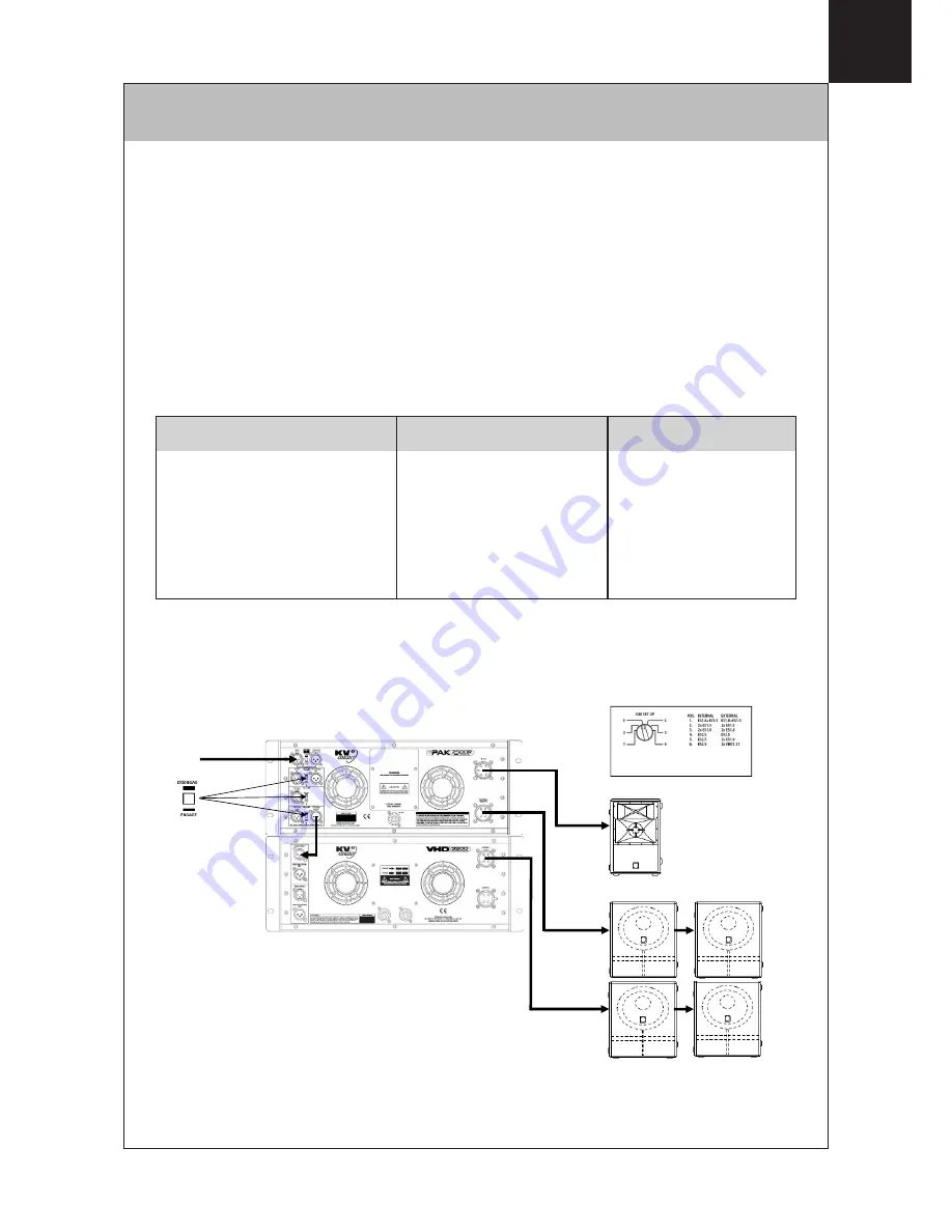
The EPAK 2500R is designed to actively power one ES 1.0 cabinet and associated subwoofer
systems. For Normal Mode operation signal is applied to the ‘Main Input’ connector and all the
‘Insert’ switches would be in the ‘Disengage’ position.
The Input Z switch should be set to match the output impedance of the device feeding the
EPAK 2500R. If you are using a VHD LD4 Line Driver then the Input Z switch on the EPAK
2500R should be set to 50
Ω
. If when using the LD4 you are feeding more than one EPAK
2500R then they should all be set to 10k
Ω
with the last one in the signal chain set to 50
Ω
.
Six different combinations of sub woofers are accommodated for when using the EPAK 2500R.
The combinations are as follows:
‘Internal’ denotes subwoofers powered by the internal subwoofer amplifier.
‘External’ denotes subwoofers powered by an external VHD 3200 subwoofer amplifier, fed
from the EPAK 2500R’s External Sub Out connector.
EPAK 2500R Setting
Setting 1
Setting 2
Setting 3
Setting 4
Setting 5
Setting 6 (5-way system)
Internal
1 x ES1.8 + 2 x ES1.5
1
2 x ES1.5
2
2 x ES1.8
1 x ES2.5
1 x ES2.5
1 x ES2.5
External
1 x ES1.8 + 2 x ES1.5
1
2 x ES1.5
2
2 x ES1.8
1 x ES2.5
2 x ES1.8
2 x VHD1.21
3
Sub Set Up switch on front
panel at position 3
All Insert switches
in ‘Disengage’
position
Main Signal Input
ES 1.0
ES 1.8
ES 1.8
4.1 NORMAL SET UP
Содержание EPAK 2500R
Страница 1: ...EPAK 2500R OPERATOR S MANUAL EPAK 2500R CONTROLLER AMPLIFIER UNIT ...
Страница 15: ......


