


_________________________________________________________________
STOGI/STOGI REFERENCE
18
KUZMA
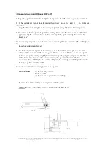
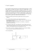
H. Bias Adjustment
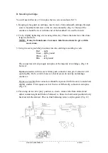
The bias should be adjusted according to the tracking force. Using cartridge protractor
provided you will see marked distance ‘x’ in grams equivalent to the tracking force. Hold
protractor as in Fig. 24. Using Allen key 1.5 mm, until in the position equivalent to your
chosen tracking force. Lock screw when in position.
For maximum trackability, it is advisable to set the bias by use of an appropriate test record,
ie. those with tracking bands. Please do not use test records with blank space where the tip of
the needle sits on the surface rather than in the groove. (Fig. 24 a)
1. Set bias and tracking force as previously described and listen to mistracking on highly
modulated
tracking bands. On higher modulated bands mistracking can be heard as impure
tones and there will be more overtones. (See instructions on test record)
2. If mistracking is apparent, increase or decrease bias until minimum mistracking is found.
If mistracking is heard on the right channel only then the bias is too low, if on both
channels the bias is too high or the trackability limit of the cartridge has been reached.
3. Finally further decrease mistracking by increasing tracking force to the maximum
recommended for the cartridge.
4. Again try to optimise bias.
NOTE: Mistracking is most easily observed by use of an osciloscope.


