


KUUMIC OY
NETWORK CONTROL
MIMIC BOARD
14
4. INSTALLATION
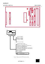
Set CPU and Display Bus Drivers DIP-switches (Figure 6 and 7)
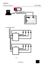
Connect the communication cable between the RKU5 control unit COM2
and the communication port of the MicroSCADA (see Figure 2).
Connect LEDs and LED power supply to the LED Control Modules
(Figure 8 and 9)
Connect IDC ribbon bus cables between RKU5 control unit and LCMs.
The IDC ribbon bus cable has 2 - 15 connectors. The number of connectors
depends on the number of LCMs and DCMs. All connectors are connected
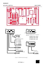
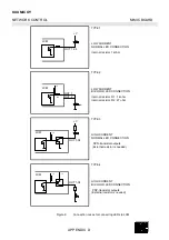
in parallel. Set card-number-select-jumpers (Figure 4 and 5). Make sure
that all LCMs and DCMs for the same bus cable are jumpered to a different
number. Install clock and data pull up jumpers (S15 and S16) to the last
LCM of the bus cable .
Note! The LCMs and the DCMs can´t be connected to the same bus cable.
Connect the RKU5 control unit and mimic board power supply on.
Use the MicroSCADA to clear NV-RAM and turn all LEDs on by writing test address
5000 dec. Check that all LEDs illuminate.
Check that all LEDs are in the correct addresses by writing them on and off
one at a time. Check the DCMs in the same way.


