Issued: 22.04.2016 Version: Spez KR 20-3 V2
4 Technical data
4.2.3
Payloads, KR 20-3
Payloads
Load center of
gravity
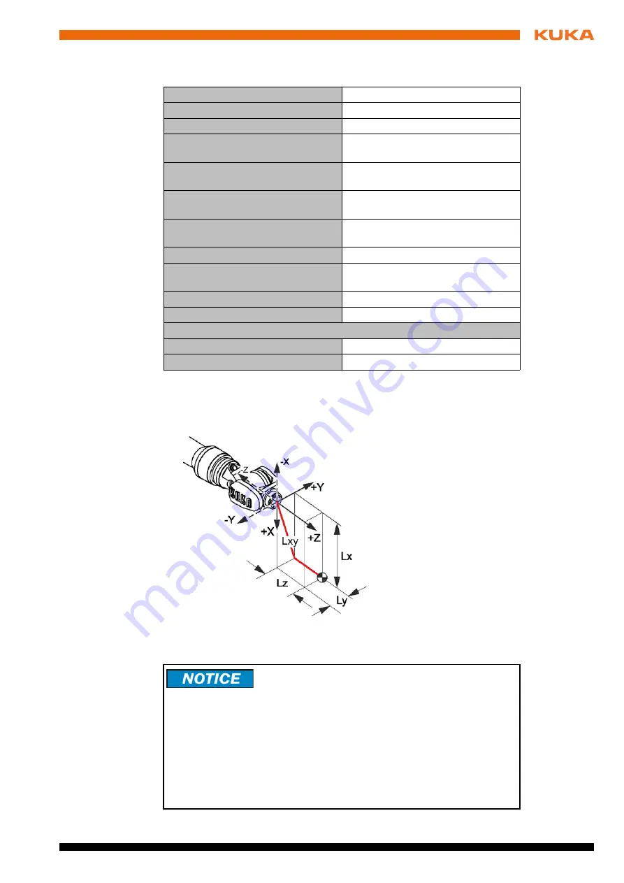
For all payloads, the load center of gravity refers to the distance from the face
of the mounting flange on axis 6. Refer to the payload diagram for the nominal
distance.
Payload diagram
Rated payload
20 kg
Rated mass moment of inertia
0.36 kgm²
Rated total load
30 kg
Rated supplementary load, base
frame
0 kg
Maximum supplementary load,
base frame
0 kg
Rated supplementary load, rotating
column
0 kg
Maximum supplementary load,
rotating column
20 kg
Rated supplementary load, link arm
0 kg
Maximum supplementary load, link
arm
20 kg
Rated supplementary load, arm
10 kg
Maximum supplementary load, arm
10 kg
Nominal distance to load center of gravity
Lxy
100 mm
Lz
120 mm
Fig. 4-4: Load center of gravity
This loading curve corresponds to the maximum load ca-
pacity. Both values (payload and mass moment of iner-
tia) must be checked in all cases. Exceeding this capacity will reduce the
service life of the robot and overload the motors and the gears; in any such
case the KUKA Roboter GmbH must be consulted beforehand.
The values determined here are necessary for planning the robot application.
For commissioning the robot, additional input data are required in accor-
dance with the operating and programming instructions of the KUKA System
Software.
The mass inertia must be verified using KUKA.Load. It is imperative for the
load data to be entered in the robot controller!
Содержание KR 20-3
Страница 6: ...6 81 Issued 22 04 2016 Version Spez KR 20 3 V2 KR 20 3...
Страница 8: ...8 81 Issued 22 04 2016 Version Spez KR 20 3 V2 KR 20 3...
Страница 12: ...12 81 Issued 22 04 2016 Version Spez KR 20 3 V2 KR 20 3...
Страница 33: ...33 81 Issued 22 04 2016 Version Spez KR 20 3 V2 4 Technical data Fig 4 20 Stopping times for STOP 1 axis 1...
Страница 35: ...35 81 Issued 22 04 2016 Version Spez KR 20 3 V2 4 Technical data Fig 4 22 Stopping times for STOP 1 axis 2...
Страница 38: ...38 81 Issued 22 04 2016 Version Spez KR 20 3 V2 KR 20 3 Fig 4 26 Stopping times for STOP 1 axis 1...
Страница 40: ...40 81 Issued 22 04 2016 Version Spez KR 20 3 V2 KR 20 3 Fig 4 28 Stopping times for STOP 1 axis 2...
Страница 42: ...42 81 Issued 22 04 2016 Version Spez KR 20 3 V2 KR 20 3...
Страница 62: ...62 81 Issued 22 04 2016 Version Spez KR 20 3 V2 KR 20 3...
Страница 68: ...68 81 Issued 22 04 2016 Version Spez KR 20 3 V2 KR 20 3...
Страница 70: ...70 81 Issued 22 04 2016 Version Spez KR 20 3 V2 KR 20 3...
Страница 78: ...78 81 Issued 22 04 2016 Version Spez KR 20 3 V2 KR 20 3...
Страница 81: ...81 81 Issued 22 04 2016 Version Spez KR 20 3 V2 KR 20 3...


