WSM U15-3
II-176
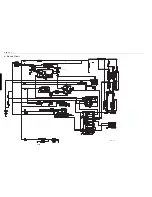
3. Route of Electric Wiring (Engine Upper Side)
(1) Glow, engine stop solenoid
(2) Unloading valve, meters, relays, etc.
(3) Key setting
(4) (Downwards) Power supply, theft-proof unit
(5) Fuse
(6) Alternator, starter motor
(7) Facing directly above
(8) Unloading: Left hole
Green-colored wire harness
Upper solenoid
(9) 2-speed:
Right hole
Yellow-colored wire harness
Lower solenoid
(10)Ground wire
(11)Connect the engine stop solenoid.
(12)Glow terminal:Tighten it to face the right side of the machine.
(13)Tighten the clamp (RP821-6738
'
) to the water flange together with the stay (wire harness 1, boom 3).
(14)Insert a clip.
(3)
(2)
(7)
(10)
(11)
(12)
(1)
(4)
(5)
(6)
(9)
(8)
(13)
(14)
Содержание u15-3
Страница 1: ...WORKSHOP MANUAL KUBOTA EXCAVATOR U15 3 Code No 97899 61270...
Страница 2: ...Record of Revisions Symbol Date Main Revised Points Corrective Measures Person in charge 1 2 3 4...
Страница 3: ...ss I Product engineering section II Service engineering section CONTENTS...
Страница 4: ......
Страница 6: ...WSM U15 3 I 2...
Страница 20: ...WSM U15 3 I 16...
Страница 65: ...WSM U15 3 II 45 b Performance curves...
Страница 72: ...WSM U15 3 II 52 g Cooling system 1 Structure Hole Clamp Cap Through Cap pressure...
Страница 83: ...WSM U15 3 II 63 3 Control Valve 2 Front Rear...
Страница 88: ...WSM U15 3 II 68 7 Inner sectional view Tightening torque T 13 7 14 7 N m T 1 4 1 5 kgf m...
Страница 130: ...WSM U15 3 II 110...
Страница 132: ...WSM U15 3 II 112 n Hydraulic circuit diagram...
Страница 170: ...WSM U15 3 II 150 8 Auto release and auto glow circuit combined Glow plug Glow lamp...
Страница 200: ...WSM U15 3 II 180...
Страница 209: ...ss Conversion Tables...
Страница 210: ......
Страница 211: ......


