


FRONT LOADER
LA525, LA765, WSM
1-S18
[2] DISASSEMBLING AND ASSEMBLING
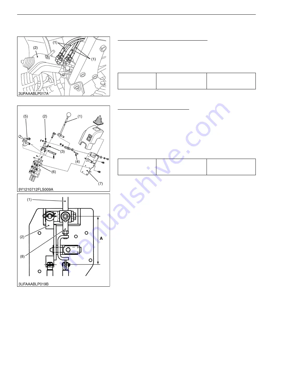
(1) Separating Control Valve Assembly
Hydraulic Hose and Control Valve Cover
1. Disconnect the hydraulic hoses (1) from the control valve.
2. Remove the control valve cover (2).
(When reassembling)
3. Assemble the control valve cover (2) to the control valve.
4. Connect the hydraulic hoses (1) to the control valve.
9Y1211014FLS0010US0
Control Lever and Control Valve
1. Disconnect the spool plate (2) and rod 1 (3) from the control
valve spools.
2. Remove the bolt (4) and remove the control lever (1).
3. Remove the control valve (6) from the valve stay (7).
(When reassembling)
• Apply LOCK-TITE 242 (Blue) to the male thread of the joint (8).
• The length
"A"
of the rod 1 (3) must be 115.3 to 116.3 mm (4.54
to 4.58 in.).
9Y1211014FLS0011US0
Tightening torque
Control valve cover
mounting bolt
9.8 to 10 N·m
1.0 to 1.1 kgf·m
7.3 to 7.9 lbf·ft
(1) Hydraulic Hose
(2) Control Valve Cover
Tightening torque
Control valve mounting bolt
24 to 27 N·m
2.4 to 2.8 kgf·m
18 to 20 lbf·ft
(1) Control Lever
(2) Spool Plate
(3) Rod 1
(4) Bolt
(5) Lever Guide
(6) Control Valve
(7) Valve Stay
(8) Joint
A: 115.3 to 116.3 mm
(4.54 to 4.58 in.)
KiSC issued 06, 2017 A
Содержание LA525
Страница 1: ...LA525 LA765 WORKSHOP MANUAL FRONT LOADER KiSC issued 06 2017 A ...
Страница 4: ...I INFORMATION KiSC issued 06 2017 A ...
Страница 10: ...INFORMATION LA525 LA765 WSM I 5 9Y1211014INI0001US0 KiSC issued 06 2017 A ...
Страница 11: ...INFORMATION LA525 LA765 WSM I 6 9Y1211014INI0002US0 KiSC issued 06 2017 A ...
Страница 20: ...G GENERAL KiSC issued 06 2017 A ...
Страница 34: ...1 FRONT LOADER KiSC issued 06 2017 A ...


