background image

GZD15, WSM

GENERAL

G-6

A

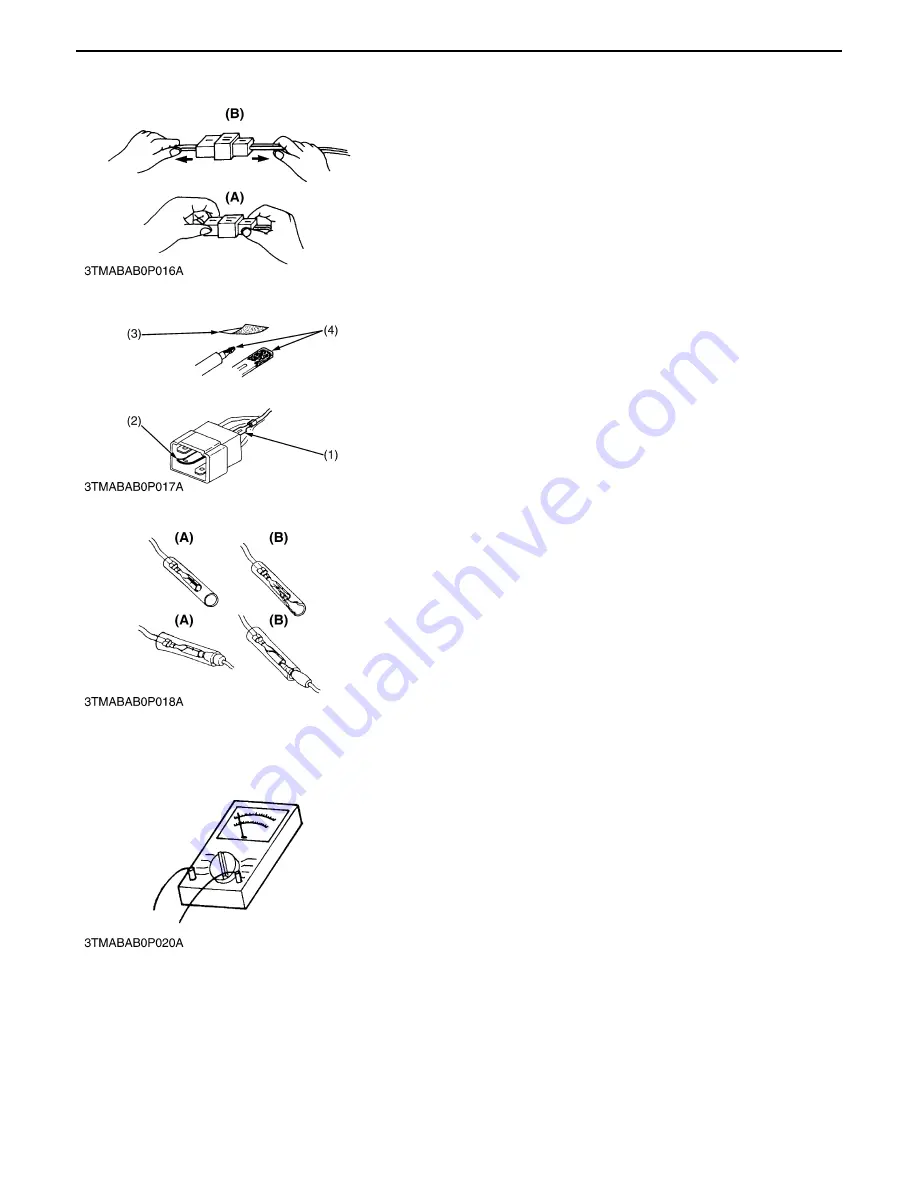
In separating connectors, do not pull wire harnesses.

A

Hold connector bodies to separate.

A

Use sandpaper to remove rust from terminals.

A

Repair deformed terminal.  Make certain there is no terminal
being exposed or displaced.

A

Make certain that there is no female connector being too open.

[5] HANDLING OF CIRCUIT TESTER

A

Use tester correctly following manual provided with tester.

A

Check for polarity and range.

(A)

Correct

(B)

Incorrect

0000000624E

(1)

Exposed Terminal

(3)

Sandpaper

(2)

Deformed Terminal

(4)

Rust

0000000625E

(A)

Correct

(B)

Incorrect

0000000626E

0000000628E

KiSC issued 04, 2006 A

Содержание GZD15

Страница 1: ...GZD15 WORKSHOP MANUAL KiSC issued 04 2006 A ...

Страница 2: ...g General includes general precautions check and maintenance and special tools Other section there are troubleshooting checking and adjusting disassembling and assembling and servicing which cover procedures precautions factory specifications and allowable limits All information illustrations and specifications contained in this manual are based on the latest product information available at the t...

Страница 3: ...ositions A Never start the engine while standing on ground Start the engine only from operator s seat This symbol the industry s Safety Alert Symbol is used throughout this manual and on labels on the machine itself to warn of the possibility of personal injury Read these instructions carefully It is essential that you read the instructions and safety regulations before you attempt to repair or us...

Страница 4: ...ng Otherwise hot water will spout out from radiator Only remove radiator cap when cool enough to touch with bare hands Slowly loosen the cap to first stop to relieve pressure before removing completely A Escaping fluid fuel or hydraulic oil under pressure can penetrate the skin causing serious injury Relieve pressure before disconnecting hydraulic or fuel lines Tighten all connections before apply...

Страница 5: ... eyes hands and clothing If you spill electrolyte on yourself flush with water and get medical attention immediately DISPOSE OF FLUIDS PROPERLY A Do not pour fluids into the ground down a drain or into a stream pond or lake Observe relevant environmental protection regulations when disposing of oil fuel coolant electrolyte and other harmful waste PREPARE FOR EMERGENCIES A Keep a first aid kit and ...

Страница 6: ...CTIONS 4 The following safety decals are installed on the machine If a decal becomes damaged illegible or is not on the machine replace it The decal part number is listed in the parts list SAFETY DECALS KiSC issued 04 2006 A ...

Страница 7: ...GZD15 WSM SAFETY INSTRUCTIONS 5 KiSC issued 04 2006 A ...

Страница 8: ...GZD15 WSM SAFETY INSTRUCTIONS 6 KiSC issued 04 2006 A ...

Страница 9: ...GZD15 WSM SAFETY INSTRUCTIONS 7 0000001495E KiSC issued 04 2006 A ...

Страница 10: ...er pump Lubricating oil API Service classification CD CE or CF below 0 32 SAE 10W 10W 30 or 10W 40 0 to 25 32 to 77 SAE 20 10W 30 or 10W 40 above 25 77 SAE 30 10W 30 or 10W 40 Starting system Electrical starter 12 V 1 1 kW Battery 65D23L 12V 52A H at 5H R Fuel No 2 D Diesel fuel ASTM D975 No 1 D diesel fuel if temperature is below 10 14 Capacities Fuel tank 20 L 5 3 U S gals 4 4 lmp gals Engine cr...

Страница 11: ...ith mower 1195 mm 47 1 in Overall height without ROPS 1115 mm 43 9 in 1345 mm 53 0 in Wheel base 1285 mm 50 6 in Tread Front 815 mm 32 1 in Rear 950 mm 37 4 in 850 mm 32 7 in Weight with mower deck and grass collector 510 kg 1124 6 lbs with 40 in mower deck 540 kg 1190 7 lbs with 40 in mower deck 0000001497E KiSC issued 04 2006 A ...

Страница 12: ...GZD15 WSM DIMENSIONS 10 DIMENSIONS KiSC issued 04 2006 A ...

Страница 13: ...GZD15 WSM DIMENSIONS 11 0000001694E KiSC issued 04 2006 A ...

Страница 14: ...G GENERAL KiSC issued 04 2006 A ...

Страница 15: ... WITH UNC OR UNF THREADS G 10 4 PLUGS G 10 6 MAINTENANCE G 11 7 CHECK AND MAINTENANCE G 13 1 DAILY CHECK G 13 2 CHECK POINTS OF INITIAL 50 HOURS G 19 3 CHECK POINT OF INITIAL 100 HOURS G 24 4 CHECK POINTS OF EVERY 50 HOURS G 25 5 CHECK POINTS OF EVERY 100 HOURS G 30 6 CHECK POINT OF EVERY 150 HOURS G 34 7 CHECK POINTS OF EVERY 200 HOURS G 34 8 CHECK POINTS OF EVERY 400 HOURS G 36 9 CHECK POINTS OF...

Страница 16: ...tributor always specify engine serial number 3 machine serial number 2 mower serial number 4 and hour meter reading 1 Machine Identification Plate 4 Mower Serial Number 2 Machine Serial Number 5 Mower Identification Plate 3 Engine Serial Number 0000001409E KiSC issued 04 2006 A ...

Страница 17: ...y KUBOTA genuine parts for parts replacement to maintain machine performance and to assure safety A Gaskets and O rings must be replaced during reassembly Apply grease to new O rings or oil seals before assembling See the figure left side A When reassembling external snap rings or internal snap rings they must be positioned so that sharp edge faces against the direction from which a force is appli...

Страница 18: ...heck for a fee A Do not attempt to modify or remodel any electrical parts and wiring A When removing the battery cables disconnect the negative cable first When installing the battery cables connect the positive cable first 1 WIRING A Securely tighten wiring terminals A Do not let wiring contact dangerous part A Securely insert grommet 1 Negative Terminal 2 Positive Terminal 0000000613E 1 Correct ...

Страница 19: ...A In installing a part take care not to get wiring caught by it A After installing wiring check protection of terminals and clamped condition of wiring only connect battery 1 Clamp 3 Clamp Wind Clamp Spirally 4 Welding Dent 2 Wire Harness 0000000617E 1 Wiring A Correct 2 Clamp B Incorrect 0000000618E 1 Wiring A Incorrect 0000000619E 1 Cover Securely Install Cover 0000000620E KiSC issued 04 2006 A ...

Страница 20: ...and clothes If contaminated wash it off with water immediately A Before recharging the battery remove it from the machine A Before recharging remove cell caps A Do recharging in a well ventilated place where there is no open flame nearby as hydrogen gas and oxygen are formed 3 FUSE A Use fuses with specified capacity Neither too large or small capacity fuse is acceptable A Never use steel or coppe...

Страница 21: ...ere is no terminal being exposed or displaced A Make certain that there is no female connector being too open 5 HANDLING OF CIRCUIT TESTER A Use tester correctly following manual provided with tester A Check for polarity and range A Correct B Incorrect 0000000624E 1 Exposed Terminal 3 Sandpaper 2 Deformed Terminal 4 Rust 0000000625E A Correct B Incorrect 0000000626E 0000000628E KiSC issued 04 2006...

Страница 22: ...4 L 1 5 U S qts 1 2 lmp qts Fresh clean water with anti freeze Recovery tank 0 25 L 0 26 U S qts 0 22 lmp qts 3 Engine crankcase 2 1 L 2 2 U S qts 1 8 lmp qts Engine oil API service classification CD CE or CF Below 0 32 SAE10W 10W 30 or 10W 40 0 to 25 32 to 77 SAE20 10W 30 or 10W 40 Above 25 77 SAE30 10W 30 or 10W 40 4 Transmission case and rear axle gear case RH and LH 10 0 L 2 6 U S gals 2 2 lmp...

Страница 23: ... grease 8 Centre pin 1 9 King pin 2 10 Front wheel 2 11 Front PTO drive shaft 2 12 Engine universal joint 1 13 Motion control lever Moderate amount oil Oil 14 Seat adjuster 15 Hydraulic lift pedal 16 Cable 17 Grass collector link Greasing Mower 18 Universal joint 3 Until grease overflows SAE multi purpose type grease 19 Two spindle shafts 2 0000001411E KiSC issued 04 2006 A ...

Страница 24: ...to 32 5 60 9 to 70 6 6 2 to 7 2 44 9 to 52 0 M12 12 mm 0 47 in 62 8 to 72 5 6 4 to 7 4 46 3 to 53 5 77 5 to 90 2 7 9 to 9 2 57 2 to 66 5 62 8 to 72 5 6 4 to 7 4 46 3 to 53 5 103 to 117 10 5 to 12 0 76 0 to 86 7 M14 14 mm 0 55 in 108 to 125 11 0 to 12 8 79 6 to 92 5 124 to 147 12 6 to 15 0 91 2 to 108 167 to 196 17 0 to 20 0 123 to 144 M16 16 mm 0 63 in 167 to 191 17 0 to 19 5 123 to 141 197 to 225...

Страница 25: ...60 0 to 192 0 5 8 203 4 to 244 1 20 75 to 24 91 150 0 to 180 0 298 3 to 358 0 30 44 to 36 53 220 0 to 264 0 0000001414E Shape Size Material of opponent part Ordinariness Aluminum ft lbs ft lbs Tapered screw R1 8 12 7 to 21 6 1 3 to 2 2 9 4 to 15 9 12 7 to 19 6 1 3 to 2 0 9 4 to 15 4 R1 4 24 5 to 44 1 2 5 to 4 5 18 1 to 32 5 24 5 to 34 3 2 5 to 3 5 18 1 to 25 4 R3 8 49 0 to 88 3 5 0 to 9 0 36 2 to ...

Страница 26: ...id Check every 50Hr G 29 Change every 150Hr G 29 7 Front axle pivot Adjust every 200Hr G 24 2 8 Safety device Check every 50Hr G 25 9 Oiling every 50Hr G 28 10 Greasing without mower every 50Hr G 27 11 Mower gear box oil Check every 50Hr G 26 Change every 150Hr G 34 12 Air cleaner element Clean every 50Hr G 26 1 Replace every 1 year G 36 13 Battery condition Check every 50Hr G 32 14 Fan belt Adjus...

Страница 27: ...37 22 Mower gear box seal Replace every 2 years G 39 2 23 Fuel system Bleed Service as required G 42 24 Fuse Replace G 40 25 Blade Replace G 41 26 Mower belt Replace G 42 A The jobs indicated by must be done initially A 1 This maintenance should be done daily more often in dusty condition than in normal conditions Suggested cleaning interval is every 100 hours in normal conditions A 2 These items ...

Страница 28: ...4 Transmission fluid level 5 Coolant level in the recovery tank 6 Damage of machine body tightness of all bolts and nuts 7 Radiator screen 8 Panel screen 9 Brake play 10 Air cleaner 11 Fuel level 12 Oiling A Mower 1 Oil leak 2 Make sure blade cap screws are tight 3 Check blades for wear or damage 4 Check all hardware 5 Make sure all pins are in place 6 Mower deck cleaning 7 Greasing A While sittin...

Страница 29: ...place it and draw it out again Check to see that the oil level is between the two notches 4 Add new oil to the prescribed level at the oil port if necessary 5 When using a different brand or viscosity oil from the previous one remove all of the old oil and oil filter Never mix two different types of oil 6 Use the proper Engine Oil SAE according to the ambient temperatures See page G 7 1 Engine Oil...

Страница 30: ...ys use a strainer when refueling to prevent fuel injection pump contamination A No 2 D is a distillate fuel of lower volatility for engines in industrial and heavy mobile service SAE J313 JUN87 Grade of Diesel Fuel Oil according to ASTM D975 Fuel tank capacity 20L 5 3 U S gals 4 4 Imp gals Flash point Water and Sediment volume Carbon Residue on 10 percent Residuum Ash weight Min Max Max Max 52 0 0...

Страница 31: ...haff has accumulated inside of the panel remove the radiator screen and clean inside completely After cleaning replace the radiator screens properly A When assembling the panel screen be sure to fit it in the runners Checking Tyre Pressure A Do not attempt to mount a tyre on a rim This should be done by a qualified person with the proper equipment A Always maintain the correct tyre pressure Inflat...

Страница 32: ...e radiator cap when the engine is hot Then loosen cap slightly to the stop to relieve any excess pressure before removing cap completely 1 Check to see that the coolant level is between the FULL and LOW marks of recovery tank 2 When the coolant level drops due to evaporation add water only up to the full level of the recovery tank In case of leakage add anti freeze and water in the specified mixin...

Страница 33: ...e Nipple A Be sure to stop the engine and remove the key before greasing 1 Apply grease to the following location as figures 1 Engine Universal Joint 3 Front PTO Drive Shaft 2 Mower Universal 4 Spindle Shaft 0000001424E KiSC issued 04 2006 A ...

Страница 34: ...th the new oil up to the upper notch on the dipstick 7 6 To check the oil level remove the dipstick 7 wipe it clean insert it and draw it out again Check to see that the oil level is between two marks A When using an oil of different manufacture or viscosity from the previous one remove all of the oid oil A Never mix two different type of oil A Use the proper SAE engine oil according to ambient te...

Страница 35: ...artridge A Be sure to stop the engine before changing the oil filter cartridge A Allow transmission case to cool down sufficiently oil can be hot and may cause burns 1 The transmission oil filter cartridge 1 must be changed every 300 service hours 2 Remove the oil filter cartridge 1 with the filter wrench 3 Lightly tighten the screw 2 by using a screwdriver 4 Apply a slight coat of oil onto the ca...

Страница 36: ...e filler plug 5 Remove the oil plug and breather cup 6 and fill with the new oil 6 After running the engine for a few minutes stop it and check the oil level again add oil to the prescribed level A Use only multi grade transmission oil Use of other oils may damage the transmission or hydraulic system Refer to LUBRICANTS FUEL AND COOLANT See page G 7 A Operate only at low RPM s immediately after ch...

Страница 37: ...smission and Rear Axle Gear Case RH and LH Fluid Continued 4 Rear Axle Gear Case A Oil level acceptable within 5 Oil Filler Plug this range 6 Oil Plug and Breather Cup 7 Dipstick 8 Transmission Oil Filter 0000001430E KiSC issued 04 2006 A ...

Страница 38: ...etely clean off filings Check O ring 3 replace if damaged cracked or hardened When reassembling be careful not to damage the parts A Since the fine filings in the oil can damage the precision component parts of the hydraulic system the end of the suction line is provided with an oil strainer 1 Strainer 3 O ring 2 Suction Line 0000001431E KiSC issued 04 2006 A ...

Страница 39: ...t within the factory specifications adjust with the slotted nut 2 4 Set the centre pin setting spring pin 4 to the centre pin 3 When reassembling Grease nipple of centre pin should be installed to upside Front axle rocking force Factory spec 9 8 to 147 1 1 0 to 15 7 2 to 108 5 ft lbs 1 Front Axle 4 Centre Pin Setting Spring Pin 2 Slotted Nut 5 Grease Nipple 3 Centre Pin 0000001428E KiSC issued 04 ...

Страница 40: ...ly set the parking brake 2 Shift the PTO lever 4 to DISENGAGE OFF position 3 Grasp the motion control levers 3 and move then inward from NEUTRAL LOCK position to NEUTRAL position and then release the levers 4 Turn the key switch 5 to START position 5 The engine must not crank B Test 4 OPERATOR ON THE SEAT 1 Securely set the parking brake 2 Shift the PTO lever 4 to ENGAGE ON position 3 Grasp the mo...

Страница 41: ... 2 1 30 psi A Operating in dusty conditions requires more frequent maintenance A Align the arrow marks when reinstalling the air cleaner cover Checking Mower Gear Box Oil Level A Always stop the engine and remove the key before checking oil 1 Park the machine on a flat surface and lower the mower to the ground To check the oil level loosen check plug bolt and check to see that the oil level is jus...

Страница 42: ...se Nipple 1 Apply a grease to the following position as figures A Be sure to stop the engine and remove the key before greasing 1 Centre Pin 3 Front Wheel LH RH 2 King Pin LH RH 4 Motion Control Lever Boss LH RH 0000001436E KiSC issued 04 2006 A ...

Страница 43: ...ove the key before greasing Reference A Grass container control cables 6 shown below are adopted to GZD15 HD E Serial No Below 10736 1 Motion Control Lever LH RH 4 Front Link 2 Seat Adjuster 5 Hydraulic Lift Pedal Oil 3 Throttle Cable Oil 6 Grass Container Control Cables for HD Oil 0000001437E KiSC issued 04 2006 A ...

Страница 44: ...ngine and remove the key before checking oil 1 Park the machine on a flat surface and lower the mower to the ground To check the oil level loosen check plug bolt 2 and check to see that the oil level is just below the check plug port If the level is too low add new oil to the prescribed level at the inlet See page G 7 1 Grass Collector Link Oil 3 Grass Collector Control Cables 2 Grass Collector Li...

Страница 45: ...ver comes first 1 The fuel lines is made of rubber and ages regardless of service period 2 If the fuel line and clamps are found damages or deteriorated replace them 3 Check fuel filter if it is clogged by debris and replace it A When the fuel line is disconnected for maintenance or repair close both ends of the fuel line with a piece of clean cloth or paper to prevent dust and dirt from entering ...

Страница 46: ...cking or adjusting A Park the machine on a hard and level surface A Wrong adjustment may cause machine damage B Check 1 Apply parking brake and check the length A of the brake spring 2 2 If it is not correct turn the lock nut 3 in the desireddirection until the proper length is achieved B Check on the slope 1 Place the machine on the under 17 ramp 2 Apply the parking brake fully 3 Place the motion...

Страница 47: ...ice life and adds to maintenance costs The original battery is a maintenance free non accessible type battery If the battery 1 is weak the engine will be difficult to start and the lights will become dim It is important to check the battery 1 periodically B How to read the indicator Check the battery condition by reading the indicator 2 State of indicator display Green Specific gravity of electrol...

Страница 48: ...arge is only for emergencies It will partially charge the battery at a high rate and in a short time When using a boost charged battery it is necessary to recharge the battery as early as possible Failure to do this will shorten the battery s service life 3 The battery is charged if the indicator display turns green from black 4 When exchanging an old battery for a new one use battery of equal spe...

Страница 49: ...ining reinstall the oil filler plug 1 3 Fill with the new oil up to the filler plug port See page G 7 4 After filling reinstall the oil filler plug 1 7 CHECK POINTS OF EVERY 200 HOURS Replacing Engine Oil Filter Cartridge 1 See page G 20 Changing Transmission and Rear Axle Case Fluid 1 See page G 21 Replacing Transmission Oil Filter Cartridge 1 See page G 20 Mower gear box oil capacity 0 15 L 0 16...

Страница 50: ...ep the engine unloaded idling A Don t stop the engine suddenly but stop it after about 5 minutes of unloaded idling A Keep yourself well away from the machine for further 10 minutes or while the steam is blown out A Checking that there gets no danger such as burning get rid of the causes of overheating and then start the engine again Checking Hydraulic Hose A Be sure to stop the engine and remove ...

Страница 51: ...r uses a dry element never apply oil A Do not run the engine with filter element removed A Be sure to refit the air cleaner cover 1 as shown in the figure If the air cleaner cover 1 is improperly fitted evacuator valve 3 will not function and dust will adhere to the element A If it is loose dust and dirt may be sucked in wearing down the cylinder and piston rings earlier and thereby resulting in p...

Страница 52: ...level is just below the port Install the radiator cap 1 securely 7 Fill with coolant up to FULL mark on the recovery tank 8 Start and operate the engine for a few minutes 9 Stop the engine and let cool Check coolant level of recovery tank 2 and add coolant if necessary A Do not start engine without coolant A Use clean fresh water and anti freeze to fill the radiator and recovery tank A When the an...

Страница 53: ...i freeze is mixed with water the anti freeze mixing ratio must be less than 50 5 Adding the LLC 1 Add only water if the mixture reduces in amount by evaporation 2 If there is a mixture leak add the LLC the same manufacture and type in the same mixture percentage Never add any long life coolant of different manufacture Different brands may have different additive components and the engine may fail ...

Страница 54: ...er to Checking Fuel Lines and Fuel Filter See page G 30 Replacing Radiator Hose 1 Replace the hoses and clamps Refer to Checking Radiator Hose and Hose Clamp See page G 35 Replacing Mower Gear Box Oil Seals 1 Replace the mower gear box oil seals 1 2 Refer to Disassembling Gear Box Assembly See page 6 S8 0000001459E 0000001460E 0000001461E 1 Oil Seal 2 Oil Seal 0000001462E KiSC issued 04 2006 A ...

Страница 55: ...low fuse 5 Place a new fuse of the same capacity in position A Before replacing a blown fuse determine why the fuse blew and make any necessary repairs Failure to follow this procedure may result in serious damage to the electrical system B Protected Circuit Fuse No ID Label Capacity A Protected circuit 1 20A Engine stop 15A Charge system 15A Aux outlet 15A Main system 10A Control system 2 Slow bl...

Страница 56: ... The blade screw 2 has left hand threads turn clockwise to loosen A Use the proper size box or socket wrench to tighten or loosen the blade mounting bolt 4 To sharpen the blades yourself clamp the blade securely in a vise Use a large mill file and file along the original bevel until sharp 5 To check the blade for balance place a small rod though the centre hole If the blade is not balanced file th...

Страница 57: ...stem Air must be removed 1 When the fuel filter or lines are removed 2 When tank is completely empty 3 After the tractor has not been used for a long period of time Bleeding procedure is as follows 1 Fill the fuel tank with fuel 2 Turn the key switch to ON position for about 30 seconds Doing so allows fuel pump 1 to work and pump air out of the fuel system 3 Start the engine and run for about 30 s...

Страница 58: ...ve both rear wheels 3 Place the motion control lever 1 in the NEUTRAL LOCK position A 4 Pull the lever of seat frame then raise and latch the seat assembly 5 Remove the connector from the seat safety switch then temporarily install a jumper wire across the terminal in the connector of the wiring harness A Do not operate the machine with a jumper wire 6 Loosen the lock nut 3 of the motion control r...

Страница 59: ...y B Reverse RETURN Position Adjustment 1 Lift up and secure with jack stands or blocking the rear of the machine frame 2 Remove both rear wheels 3 Start the engine and run at maximum speed 4 Place the motion control lever 1 in the NEUTRAL position B 5 Pull the motion control lever 1 to the reverse maximum position and release the lever 6 Check if the axle rotate or not 7 If the axle rotate loosen ...

Страница 60: ...CONTROL LEVER POSITION They are relation each other A Right and left motion control levers can be adjusted independently B Maximum Speed Forward 1 Lift up and secure with jack stands or blocking the rear of the machine frame 2 After starting the engine keep the engine speeds to the maximum 3 Place the motion control lever 1 in the MAXIMUM FORWARD position 4 Check both rear wheels rotation with a d...

Страница 61: ...he motion control lever position high or low Lever alignment Right and left 4 Loosen the bolts 3 5 Slide both levers forward or reward to desired position within tab slots until levers are aligned 6 Tighten the bolts 3 A If the ends of the levers strike against each other while in the NEUTRAL position move the levers outward to the NEUTRAL LOCK position and carefully bend them outward Move them ba...

Страница 62: ...end 2 Turn the cutting height set dial to the 3 in cutting height position 3 Lower the mower deck 4 Position the right mower blade 1 in the Side to Side position 5 Measure from outside blade tip to the level surface with a short ruler or leveling gauge Reference A There is a difference of the blade height between on the concrete and ground 6 Check that the left side blade is same height The differ...

Страница 63: ...ight wood blocks under each side of the mower deck 4 Lower the mower deck 5 Position mower blade 1 in the Side to Side position 6 Loosen the lock nuts of the right side of the machine 7 Adjust the cutting height fine turning bolts to set 80 mm height 8 Lock the nuts 9 Adjust the left side equally 10 Check the side to side level and if it is not level adjustment necessary 1 Blade A Side 2 Cutting H...

Страница 64: ...ear blade tip to the level surface 7 Check that the left side blade has the same dimension The difference between both measurement should be less than 6 mm 0 24 in Front side must be lower than rear side 8 If the Front to Rear adjustment is not within the given tolerance adjustment necessary B Adjusting level Front to Rear 1 Raise up the mower deck to the transport position Also the top end 2 Turn...

Страница 65: ...e No 07909 32121 Application Use exclusively for removing or installing the piston ring with ease Diesel Engine Compression Tester Code No 07909 30208 Assembly 07909 31251 G 07909 30934 A to F 07909 31271 I 07909 31211 E and F 07909 31281 J 07909 31231 H Application Use to measure diesel engine compression and diagnostics of need for major overhaul 0000000677E 0000000678E 0000000679E 1 Gauge 7 Ada...

Страница 66: ...ter Code No 07909 31551 Application Use to check of radiator cap pressure and leaks from cooling system Remarks Adaptor 1 BANZAI Code No RCT 2A 30S Connecting Rod Alignment Tool Code No 07909 31661 Application Use to check the connecting rod alignment Applicable Connecting rod big end I D range 30 to 75 mm 1 18 to 2 95 in dia Connecting rod length 65 to 300 mm 2 56 to 11 81 in 1 Gauge 5 Adaptor 2 ...

Страница 67: ... MPa range 0 to 500 0 to 7000 psi Plastigage Code No 07909 30241 Application Use to check the oil clearance between crankshaft and bearing etc Measuring Green 0 025 to 0 076 mm 0 001 to 0 003 in range Red 0 051 to 0 152 mm 0 002 to 0 006 in Blue 0 102 to 0 229 mm 0 004 to 0 009 in Red Check Code No 07909 31371 Application Use to check cracks on cylinder head cylinder block etc 0000001473E 00000006...

Страница 68: ...ia B 9 96 to 9 98 mm dia 0 3921 to 0 3929 in dia C 5 5 to 5 7 mm dia 0 2165 to 0 2244 in dia D 200 mm 7 87 in E 80 mm 3 15 in F 40 mm 1 58 in G 15 mm 0 59 in H 5 mm 0 197 in I 6 0 to 6 1 mm dia 0 263 to 0 240 in dia J 18 mm dia 0 71 in dia K 10 6 to 10 7 mm dia 0 417 to 0 421 in dia L 7 mm 0 276 in C1 Chamfer 1 0 mm 0 039 in C2 Chamfer 2 0 mm 0 079 in C0 3 Chamfer 0 3 mm 0 012 in 0000001474E KiSC ...

Страница 69: ... F PF 1 2 G 5 mm 0 20 in H 17 mm dia 0 67 in dia I 8 mm dia 0 31 in dia J 1 0 mm 0 039 in K 17 mm dia 0 67 in dia L 6 10 to 6 20 mm dia 0 2402 to 0 2441 in dia M 8 mm 0 31 in N 4 mm 0 16 in O 11 97 to11 99 mm dia 0 4713 to 0 4721 in dia P PF 1 2 Q 23 mm 0 91 in R 17 mm 0 67 in S 4 mm 0 16 in T 12 00 to 12 02 mm dia 0 4724 to 0 4732 in dia U 100 mm 3 94 in V M12 x P1 5 a Adhesive application b Fill...

Страница 70: ...b 6 3 250 A 150 mm 5 91 in B 20 mm 0 79 in C 100 mm 3 94 in D 19 90 to 19 95 mm 0 7835 to 0 7854 in E 21 90 to 21 95 mm dia 0 8622 to 0 8642 in dia F 25 mm 0 98 in a 6 3 250 b 6 3 250 0000001476E Press Out A 135 mm 5 31 in B 72 mm 2 83 in C 1 57 rad 40 D 10 mm 0 39 in E 22 mm 0 87 in F 20 mm dia 0 79 in dia G 48 90 to 48 95 mm dia 1 9251 to 1 9271 in dia H 43 90 to 43 95 mm dia 1 7283 to 1 7303 in...

Страница 71: ... of relief set pressure 1 Gauge 07916 50322 6 Adaptor C PS3 8 2 Cable 07916 50331 07916 50371 3 Threaded Joint 7 Adaptor D PT1 8 07916 50401 07916 50381 4 Threaded Joint 8 Adaptor E PS3 8 07916 50341 07916 50392 5 Adaptor B M18 x P1 5 9 Adaptor F PF1 2 07916 50361 07916 62601 10 Adaptor 58 PT1 4 07916 52391 0000000705E KiSC issued 04 2006 A ...

Страница 72: ...1 ENGINE KiSC issued 04 2006 A ...

Страница 73: ...CONTENTS 1 ENGINE BODY 1 M1 1 HALF FLOATING HEAD COVER 1 M1 2 GEAR CASE 1 M1 3 OIL PAN 1 M2 2 LUBRICATING SYSTEM 1 M3 3 COOLING SYSTEM 1 M4 4 FUEL SYSTEM 1 M5 1 FUEL LINE 1 M5 KiSC issued 04 2006 A ...

Страница 74: ...d This arrangement helps reduce noise coming from the cylinder head 2 GEAR CASE The engine has a gear case where the cooling fins are set up around the oil passage Therefore the temperature of engine oil is decreased by the wind generated by the cooling fan 1 Cylinder Head Cover 2 Rubber Packing 0000005017E 1 Cooling Fins 0000005018E KiSC issued 04 2006 A ...

Страница 75: ...IL PAN The oil pan is expanded under the gear case Therefore the height of the engine can be lowered more than so far while securing a necessary amount of oil 1 Gear Case 3 Crank Case 2 Oil Pan 0000005019E KiSC issued 04 2006 A ...

Страница 76: ...6 connecting rods 14 idle gear 5 camshaft 12 and rocker arm shaft 3 to lubricate each part Some part of oil splashed by the crankshaft or leaking and dropping from gaps of each part lubricates these parts piston 13 cylinders small ends or connecting rods tappets 11 push rods 10 inlet and exhaust valves 4 and timing gears 1 Rocker Arm 2 Oil Pressure Switch 3 Rocker Arm Shaft 4 Valve 5 Idle Gear 6 C...

Страница 77: ... water pump receives water from the radiator or from the cylinder head and force it into the cylinder block The thermostat opens or closes according to the water temperature When the water temperature is high the thermostat opens to allow the water to flow from the cylinder head to the radiator When the water temperature is low the thermostat close to flow the water only to the water pump 1 Radiat...

Страница 78: ...MPa 140 to 150 1990 to 2133 psi of the injection nozzle 1 is injected into the combustion chamber Part of the fuel fed to the injection nozzle 1 lubricates the moving parts of the needle valve inside the nozzle then returns to the fuel tank through the fuel overflow pipe 2 from the upper part of the nozzle holder 1 Injection Nozzle 2 Fuel Overflow Pipe 3 Fuel Tank 4 Fuel Filter 5 Fuel Feed Pump 6 ...

Страница 79: ...aining Coolant and Engine Oil 1 S10 2 ENGINE BODY 1 S16 1 Checking and Adjusting 1 S16 2 Disassembling and Assembling 1 S19 3 Servicing 1 S32 3 LUBRICATING SYSTEM 1 S50 1 Checking 1 S50 2 Servicing 1 S51 4 COOLING SYSTEM 1 S52 1 Checking and Adjusting 1 S52 2 Disassembling and Assembling 1 S54 5 FUEL SYSTEM 1 S55 1 Checking and Adjusting 1 S55 KiSC issued 04 2006 A ...

Страница 80: ...ct injection timing Adjust 1 S56 A Fuel camshaft worn Replace A Injection nozzle clogged Repair or replace 1 S59 A Injection pump malfunctioning Replace A Seizure of crankshaft camshaft piston cylinder or bearing Repair or replace A Compression leak from cylinder Replace head gasket tighten cylinder head screw glow plug and nozzle holder 1 S16 A Improper valve timing Correct or replace timing gear...

Страница 81: ...logged Replace G 36 A Air cleaner clogged Clean or replace G 26 36 A Deficient nozzle injection Repair or replace nozzle 1 S59 Deficient Output A Incorrect injection timing Adjust 1 S56 A Engine s moving parts seem to be seizing Repair or replace A Uneven fuel injection Replace injection pump A Deficient nozzle injection Repair or replace nozzle 1 S59 A Compression leak Replace head gasket tighten...

Страница 82: ...oil G 7 A Oil pump defective Repair or replace 1 S50 S51 High Oil Pressure A Different type of oil Use specified type of oil G 7 A Relief valve defective Replace Engine Overheated A Engine oil insufficient Replenish G 7 A Fan belt broken or tensioned improperly Replace or adjust G 31 1 S52 A Coolant insufficient Replenish G 7 A Radiator net and radiator fin clogged with dust Clean A Inside of radi...

Страница 83: ...0 057 mm 0 00118 to 0 00224 in 0 10 mm 0 0039 in Valve Stem O D 5 968 to 5 980 mm 0 23496 to 0 23543 in Valve Guide I D 6 010 to 6 025 mm 0 23661 to 0 23720 in Valve Face Angle 0 785 rad 45 Valve Seat Angle 0 785 rad 45 Width 2 12 mm 0 0835 in Valve Spring Free Length 31 3 to 31 8 mm 1 232 to 1 252 in 28 4 mm 1 118 in Tilt 1 2 mm 0 047 in Setting Load Setting Length 64 7 N 27 0 mm 6 6 kgf 27 0 mm ...

Страница 84: ...Oil Pump Drive Gear Backlash 0 041 to 0 123 mm 0 00161 to 0 00484 in 0 15 mm 0 0059 in Idle Gear Side Clearance 0 20 to 0 51 mm 0 0079 to 0 0201 in 0 80 mm 0 0315 in Camshaft Side Clearance 0 15 to 0 31 mm 0 0059 to 0 0122 in 0 50 mm 0 0197 in Alignment 0 01 mm 0 0004 in Cam Height Intake and Exhaust 26 88 mm 1 0583 in 26 83 mm 1 0563 in Camshaft Journal to Cylinder Block Bore Oil Clearance 0 050 ...

Страница 85: ...Gap Top Ring 0 20 to 0 35 mm 0 0079 to 0 0138 in 1 25 mm 0 0492 in Second Ring 0 35 to 0 50 mm 0 0138 to 0 0197 in 1 25 mm 0 0492 in Oil Ring 0 20 to 0 35 mm 0 0079 to 0 0138 in 1 25 mm 0 0492 in Piston Ring to Piston Ring Groove Second Ring Clearance 0 090 to 0 120 mm 0 00354 to 0 00472 in 0 15 mm 0 0059 in Oil Ring Clearance 0 04 to 0 08 mm 0 0016 to 0 0031 in 0 15 mm 0 0059 in Connecting Rod Al...

Страница 86: ...Clearance 0 028 to 0 059 mm 0 00110 to 0 00232 in 0 20 mm 0 0079 in Crankshaft Journal O D 43 934 to 43 950 mm 1 72968 to 1 73031 in Crankshaft Bearing 3 I D 43 978 to 43 993 mm 1 73142 to 1 73201 in Cylinder Liner Standard I D 72 000 to 72 019 mm 2 83464 to 2 83539 in 72 169 mm 2 84129 in Cylinder Liner Oversize 0 25 mm 0 0098 in I D 72 500 to 72 519 mm 2 85433 to 2 85507 in 72 669 mm 2 86098 in ...

Страница 87: ...e No leaks at specified pressure 157 kPa 1 6 23 psi 0000001405E FUEL SYSTEM Item Factory Specification Allowable Limit Injection Pump Injection Timing 0 30 to 0 33 rad 17 to 19 before T D C Pump Element Fuel Tightness 13 7 MPa 140 1990 psi Delivery Valve Fuel Tightness 10 seconds 13 7 12 7 MPa 140 130 1990 1849 psi 5 seconds 13 7 12 7 MPa 140 130 1990 1849 psi Fuel Injection Nozzle Injection Press...

Страница 88: ...linder head screw M8 x 1 25 37 3 to 42 2 3 8 to 4 3 27 5 to 31 1 Fan drive pulley screw M12 x 1 5 98 0 to 107 8 10 0 to 11 0 72 3 to 79 5 Idle gear shaft mounting screw M6 x 1 9 8 to 11 3 1 00 to 1 15 7 2 to 8 3 Connecting rod screw M7 x 0 75 26 5 to 30 4 2 7 to 3 1 19 5 to 22 4 Flywheel screw M10 x 1 25 53 9 to 58 8 5 5 to 6 0 39 8 to 43 4 Bearing case cover mounting screw M6 x 1 9 8 to 11 3 1 00...

Страница 89: ...gine for a few minutes 3 Stop the engine and let cool 4 Check coolant level of recovery tank 3 and add coolant if necessary Draining Engine Oil 1 Start and warm up the engine for approx 5 minutes 2 Place an oil pan underneath the engine 3 Remove the drain plug 1 to drain oil 4 After draining screw in the drain plug 1 When refilling A Fill the engine oil up to the upper line on the dipstick 3 A Nev...

Страница 90: ... right and the left under cover 1 Bonnet 1 Remove the bonnet 1 When reassembling Grass Collector Base 1 Disconnect the grass collector dump cylinder hoses on right side 2 Remove the pins 2 on both sides 3 Separate the grass collector base 1 1 Battery 3 Positive Cable 2 Negative Cable 0000001482E 1 Under Cover 2 Bonnet 0000001483E Tightening torque Bonnet mounting screw 7 8 to 8 8 0 8 to 0 9 5 8 to...

Страница 91: ...th seat stay 2 2 Remove the front radiator net 3 3 Remove the screw 4 and rear floor cover 3 4 Remove the screw 5 Disconnect the radiator shutter plate 6 from the machine 1 Seat 4 Rear Floor Cover 2 Seat Stay 5 Screw 3 Front Radiator Net 6 Radiator Shutter Plate 0000001669E KiSC issued 04 2006 A ...

Страница 92: ...erating wire from the engine When reassembling 1 Adjust the length L of accelerating wire 2 Lock the nut securely Fuel Hoses 1 Disconnect the overflow hose 1 2 Disconnect the fuel hose 3 1 Pin 7 ST Terminal 2 Nut 8 B Terminal 3 Stop Solenoid Connector 9 Plastic Clamp 4 Glow Plug Terminal Nut 11 Accelerating Wire 5 Thermo Sensor 6 Oil Switch L Length 0000001670E 1 Overflow Hose 3 Fuel Hose 2 Fuel F...

Страница 93: ...emove the engine mounting support screws 1 3 Disconnect the left and the right engine mounting support from the engine When reassembling Tightening torque Front coupling mounting screw 23 5 to 27 4 2 4 to 2 8 17 4 to 20 3 ft lbs 1 Screw 2 Front Coupling 0000001672E Tightening torque Engine mounting support screw 31 4 to 34 3 3 2 to 3 5 23 1 to 25 3 ft lbs 1 Screw 2 Engine Mounting Support 00000016...

Страница 94: ...hen reassembling the engine 1 Connect the front coupling 2 2 Check the wiring harness 3 and fuel pipes 4 and accelerating wire 5 as shown in picture 3 Check the hydraulic oil cooler 6 as shown in picture 1 Engine Assembly 4 Fuel Pipe 2 Front Coupling 5 Accelerating Wire 3 Wiring Harness 6 Hydraulic Oil Cooler 0000001674E KiSC issued 04 2006 A ...

Страница 95: ...measurement is below the allowable limit apply a small amount of oil to the cylinder wall through the nozzle hole and measure the compression pressure again 10 If the compression pressure is still less than the allowable limit check the top clearance valve clearance and cylinder head 11 If the compression pressure increases after applying oil check the cylinder wall and piston rings A Check the co...

Страница 96: ...ews to the specified torque 4 Turn the flywheel until the piston exceeds its top dead centre 5 Remove the cylinder head and measure the thickness of the squeezed fuses 6 If the measurement is not within the factory specifications check the oil clearance between the crankpin and crankpin bearing and between the piston pin and small end bushing A After checking the top clearance be sure to assemble ...

Страница 97: ...nment marking plate 3 on the rear end plate so that the No 1 piston comes to the overlap position 6 Check the following valve clearance marked with using a thickness gauge When No 1 piston is at the overlap position 7 If the clearance is not within the factory specifications adjust with the adjusting screw A The sequence of cylinder numbers is given as No 1 and No 2 starting from the gear case sid...

Страница 98: ...er 2 When reassembling A Check to see if the cylinder head cover gasket is not defective Injection Pipes 1 Loosen the screw on the pipe clamp 1 2 Detach the injection pipes 2 When reassembling A Sent compressed air into the pipes to blow out dust Then reassemble the pipes in the reverse order A Cylinder Head Valves and Oil Pan Tightening torque Muffler 48 0 to 55 9 4 9 to 5 7 35 4 to 41 2 ft lbs 1...

Страница 99: ...ing the push rods 3 onto the tappets 4 check to see if their ends are properly engaged with the dimples A After installing the rocker arm be sure to adjust the valve clearance Tightening torque Overflow pipe retaining nut 19 6 to 24 5 2 0 to 2 5 14 5 to 18 1 ft lbs Nozzle holder assembly 49 0 to 68 6 5 0 to 7 0 36 2 to 50 6 ft lbs Glow plug 7 85 to 14 7 0 8 to 1 5 5 8 to 10 8 ft lbs 1 Overflow Pip...

Страница 100: ...equence starting from the centre A Tighten them uniformly or the head may deform in the long run A Retighten the cylinder head screws after running the engine for 30 minutes Tappets 1 Remove the tappets 1 from the crankcase When reassembling A Visually check the contact between tappets and cams for proper rotation If defect is found replace tappets A Before installing the tappets apply engine oil ...

Страница 101: ...ve the valve 7 When reassembling A Wash the valve stem seal and valve guide hole and apply engine oil sufficiently A After installing the valve spring collets lightly tap the stem to assure proper fit with a plastic hammer A Do not change the combination of valve and valve guide 1 Valve Spring Replacer 5 Valve Spring 2 Valve Cap 6 Valve Stem Seal 3 Valve Spring Collet 7 Valve 4 Valve Spring Retain...

Страница 102: ...Using the hole 5 numbered 2 install the oil strainer by mounting screw A Scrape off the old adhesive completely Wipe the sealing surface clean Now apply new adhesive 3 to 5 mm 0 12 to 0 20 in thick all over the contact surface Apply the adhesive also on the centre of the flange as well as on the inner wall of each screw hole A Cut the nozzle of the liquid gasket Three Bond 1207D or equivalent cont...

Страница 103: ... A The sealant is applied to both sides of the soft metal gasket shim The liquid gasket is not required for assembling A Addition or reduction of shim 0 05 mm 0 0020 in delays or advances the injection timing by approx 0 0087 rad 0 5 A In disassembling and replacing be sure to use the same number of new gasket shims with the same thickness Fan Drive Pulley 1 Secure the flywheel to keep it from tur...

Страница 104: ...ear 1 Remove the external snap ring 3 the collar 2 and the idle gear 1 2 Remove the idle gear shaft mounting screws 3 Remove the idle gear shaft When reassembling A Apply engine oil to the idle gear shaft mounting screw And tighten them A Install the idle gear aligning the mark on the gears referring to the figure 1 Screw Inside 3 Gear Case 2 Start Spring 0000000860E Tightening torque Idle gear sh...

Страница 105: ...e gear See the photo at Idle Gear Connecting Rod 1 Remove the connecting rod caps 1 When reassembling A Align the marks a with each other Face the marks toward the injection pump A Apply engine oil to the connecting rod screws and lightly screw it in by hand then tighten it to the specified torque If the connecting rod screw won t be screwed in smoothly clean the threads If the connecting rod scre...

Страница 106: ... on the connecting rod to the injection pump A Do not change the combination of cylinder and piston Make sure of the position of each piston by marking For example mark 1 on the No 1 piston A When installing the piston into the cylinder place the gaps of all the piston rings as shown in the figure A Carefully insert the pistons using a piston ring compressor 1 Otherwise their chrome plated section...

Страница 107: ...to the piston immerse the piston in 80 176 oil for 10 to 15 minutes and insert the piston pin to the piston A When installing the connecting rod to the piston align the mark 8 on the connecting rod to the fan shaped concave 9 A Select the connecting rod and crankpin bearing that have their I D colour A and B just the same A Mark the same number on the connecting rod and the piston so as not to cha...

Страница 108: ...nd the bearing case cover gasket 4 with correct directions A Install the bearing case cover 6 to position the casting mark UP a on it upward A Apply engine oil to the oil seal 5 lip and take care that it is not rolled when installing A Tighten the bearing case cover mounting screws with even force on the diagonal line D Crankshaft Tightening torque Flywheel screw 53 9 to 58 8 5 5 to 6 0 39 8 to 43...

Страница 109: ...passage of the crankshaft with compressed air A Apply oil to the main bearing case screw 2 1 A Install the crankshaft assembly aligning the screw hole of main bearing case with the screw hole of crankcase Tightening torque Main bearing case screw 2 26 5 to 30 4 2 7 to 3 1 19 5 to 22 4 ft lbs 1 Main Bearing Case Screw 2 0000000871E KiSC issued 04 2006 A ...

Страница 110: ...g 3 4 5 Install the bearing with the oil groove d up A Match the alignment numbers a on the main bearing case A Do the same for the main bearing case assembly 3 too A When installing the main bearing case 1 face the mark FLYWHEEL to the flywheel A Install the thrust bearing with its oil groove facing outward A Confirm that the main bearing case moves smoothly after tightening the main bearing case...

Страница 111: ...ecting Cylinder Head Flaw 1 Prepare an air spray red check Code No 07909 31371 2 Clean the surface of the cylinder head with the detergent 2 3 Spray the cylinder head surface with the red permeative liquid 1 Leave it five to ten minutes after spraying 4 Wash away the red permeative liquid on the cylinder head surface with the detergent 2 5 Spray the cylinder head surface with the white developer 3...

Страница 112: ...ction 2 Measure the valve stem O D with an outside micrometer 3 Measure the valve guide I D with a small hole gauge and calculate the clearance 4 If the clearance exceeds the allowable limit replace the valves If it still exceeds the allowable limit replace the valve guide Valve recessing Intake and Exhaust Factory spec 0 10 protrusion to 0 10 recessing mm 0 0039 protrusion to 0 0039 recessing in ...

Страница 113: ...alve Seating 1 Coat the valve face lightly with prussian blue and put the valve on its seat to check the contact 2 If the valve does not seat all the way around the valve seat or the valve contact is less than 70 correct the valve seating as follows 3 If the valve contact does not comply with the reference value replace the valve or correct the contact of valve seating Valve guide I D Intake and E...

Страница 114: ...he seat with a 0 785 rad 45 valve seat cutter again and visually recheck the contact between the valve and seat 5 Repeat steps 3 and 4 until the correct contact is achieved 6 Continue lapping until the seated rate becomes more than 70 of the total contact area Valve Lapping 1 Apply compound evenly to the valve lapping surface 2 Insert the valve into the valve guide Lap the valve onto its seat with...

Страница 115: ...ker Arm and Rocker Arm Shaft 1 Measure the rocker arm shaft O D with an outside micrometer 2 Measure the rocker arm I D with an inside micrometer and then calculate the oil clearance 3 If the oil clearance exceeds the allowable limit replace the rocker arm and measure the oil clearance again If it still exceeds the allowable limit replace also the rocker arm shaft Free length A Factory spec 31 3 t...

Страница 116: ...ith a cylinder gauge and calculate the oil clearance 3 If the oil clearance exceeds the allowable limit or the tappet is damaged replace the tappet Push rod alignment Allowable limit 0 25 mm 0 0098 in 0000000885E Oil clearance between tappet and tappet guide bore Factory spec 0 016 to 0 052 mm 0 00063 to 0 00205 in Allowable limit 0 10 mm 0 0039 in Tappet O D Factory spec 17 966 to 17 984 mm 0 707...

Страница 117: ...measurement exceeds the allowable limit replace the camshaft stopper B Timing Gear Camshaft and Fuel Camshaft Backlash between idle gear and crank gear Factory spec 0 043 to 0 124 mm 0 00169 to 0 00488 in Allowable limit 0 15 mm 0 0059 in Backlash between idle gear and cam gear Factory spec 0 047 to 0 123 mm 0 00185 to 0 00484 in Allowable limit 0 15 mm 0 0059 in Backlash between idle gear and inj...

Страница 118: ...al O D with an outside micrometer 2 Measure the cylinder block bore I D for camshaft with a cylinder gauge and calculate the oil clearance 3 If the oil clearance exceeds the allowable limit replace the camshaft Camshaft alignment Allowable limit 0 01 mm 0 0004 in 0000000891E Cam height of intake and exhaust Factory spec 26 88 mm 1 0583 in Allowable limit 26 83 mm 1 0563 in 0000000892E Oil clearanc...

Страница 119: ...bushing using an idle gear bushing replacing tool until it is flush with the end of the idle gear Piston Pin Bore I D 1 Measure the piston pin bore I D in both the horizontal and vertical directions with a cylinder gauge 2 If the measurement exceeds the allowable limit replace the piston Oil clearance between idle gear shaft and idle gear bushing Factory spec 0 020 to 0 084 mm 0 00079 to 0 00331 i...

Страница 120: ...ng positions as shown in the figure until it is flush with the connecting rod 3 Drill a hole to the bushing with aligning the oil hole 2 of connecting rod Refer to the figure A Be sure to chamfer the oil hole circumference with an oil stone Oil clearance between piston pin and small end bushing Factory spec 0 014 to 0 038 mm 0 00055 to 0 00150 in Allowable limit 0 10 mm 0 0039 in Piston pin O D Fa...

Страница 121: ...e limit replace the piston ring 4 If the clearance still exceeds the allowable limit with new ring replace the piston Piston ring gap Top ring Factory spec 0 20 to 0 35 mm 0 0079 to 0 0138 in Allowable limit 1 25 mm 0 0492 in Second ring Factory spec 0 35 to 0 50 mm 0 0138 to 0 0197 in Allowable limit 1 25 mm 0 0492 in Oil ring Factory spec 0 20 to 0 35 mm 0 0079 to 0 0138 in Allowable limit 1 25 ...

Страница 122: ...d alignment tool Code No 07909 31661 4 Put a gauge over the piston pin and move it against the face plate 5 If the gauge does not fit squarely against the face plate measure the space between the pin of the gauge and the face plate 6 If the measurement exceeds the allowable limit replace the connecting rod Space between gauge pin face plate Allowable limit 0 05 mm 0 0020 in 0000000902E KiSC issued...

Страница 123: ...f the measurement exceeds the allowable limit replace the crankshaft D Crankshaft Crankshaft side clearance Factory spec 0 15 to 0 31 mm 0 0059 to 0 0122 in Allowable limit 0 50 mm 0 0197 in Oversize Bearing Code Number Marking 0 2 mm 0 008 in Thrust bearing 1 02 15261 23950 020 OS Thrust bearing 2 02 15261 23970 020 OS 0 4 mm 0 016 in Thrust bearing 1 04 15261 23960 040 OS Thrust bearing 2 04 152...

Страница 124: ... screws are tightened Reference A Undersize crankpin bearing A Undersize dimensions of crankpin Oil clearance between crankpin and crankpin bearing Factory spec 0 020 to 0 051 mm 0 00079 to 0 00201 in Allowable limit 0 15 mm 0 0059 in Crankpin O D Factory spec 33 959 to 33 975 mm 1 33697 to 1 33760 in Crankpin bearing I D Factory spec 33 995 to 34 010 mm 1 33893 to 1 33898 in Undersize Bearing Cod...

Страница 125: ... and crankshaft bearing 1 Factory spec 0 034 to 0 106 mm 0 00134 to 0 00417 in Allowable limit 0 20 mm 0 0079 in Crankshaft journal O D Factory spec 43 934 to 43 950 mm 1 72968 to 1 73031 in Crankshaft bearing 1 I D Factory spec 43 984 to 44 040 mm 1 73165 to 1 73386 in Undersize Bearing Code Number Marking 0 2 mm 0 008 in Crankshaft bearing 1 02 1G460 23910 020 US 0 4 mm 0 016 in Crankshaft beari...

Страница 126: ...il clearance exceeds the allowable limit replace the crankshaft bearing 2 crankshaft bearing 3 5 If the same size bearing is useless because of the crankshaft journal wear replace it with an undersize one referring to the table and figure A Be sure not to move the crankshaft while the bearing case screws are tightened Dimension A Factory spec 0 0 to 0 3 mm 0 0 to 0 0118 in 1 Seam 3 Cylinder Block ...

Страница 127: ...aring 2 04 15694 23940 040 US Crankshaft bearing 2F 04 1G460 07540 Crankshaft bearing 3 04 1G460 07590 040 US Crankshaft bearing 3F 04 1G460 07640 Undersize 0 2 mm 0 008 in 0 4 mm 0 016 in Dimension A 1 8 to 2 2 mm radius 0 071 to 0 087 in radius 1 8 to 2 2 mm radius 0 071 to 0 087 in radius Dimension B 4 mm dia 0 16 in dia 4 mm dia 0 16 in dia Dimension C 43 734 to 43 750 mm dia 1 72181 to 1 7224...

Страница 128: ...he specified dimension 2 Replace the piston and piston rings with oversize ones A When the oversize cylinder is worn beyond the allowable limit replace the cylinder block with a new one E Cylinder Cylinder I D Factory spec 72 000 to 72 019 mm 2 83464 to 2 83539 in Allowable limit 72 169 mm 2 84129 in A Top a Right angled to Piston Pin B Middle b Piston Pin Direction C Bottom Skirt 0000001678E Cyli...

Страница 129: ...ollowing A Engine oil insufficient A Oil pump defective A Oil strainer clogged A Oil filter cartridge clogged A Oil gallery clogged A Excessive oil clearance A Foreign matter in the relief valve When reassembling A After checking the engine oil pressure tighten the engine oil pressure switch to the specified torque Engine oil pressure At idle speed Factory spec More than 49 kPa 0 5 7 psi At rated ...

Страница 130: ...mbly Clearance between Rotor and Cover 1 Put a strip of plastigage Code No 07909 30241 onto the rotor face with grease 2 Install the cover and tighten the screws 3 Remove the cover carefully and measure the amount of the flattening with the scale and get the clearance 4 If the clearance exceeds the factory specifications replace the oil pump rotor assembly Rotor lobe clearance Factory spec 0 03 to...

Страница 131: ...s nearly worn out and deeply sunk in the pulley groove replace it Thermostat Valve Opening Temperature 1 Suspend the thermostat in the water by a string with its end inserted between the valve and seat 2 Heating the water gradually read the temperature when the valve opens and leaves the string 3 Continue heating and read the temperature when the valve opens approx 8 mm 0 315 in 4 If the measureme...

Страница 132: ...o RCT 2A 30S and raise the water pressure to the specified pressure 3 Check the radiator for water leaks 4 For water leak from the pinhole repair with the radiator cement When water leak is excessive replace the radiator A When removing the radiator cap wait at least ten minutes after the engine has stopped and cooled down Otherwise hot water way gush out scalding nearby people 0000000922E Pressur...

Страница 133: ...ve the fan and fan pulley 3 Remove the water pump assembly from the gear case cover 4 Remove the water pump flange 1 5 Press out the water pump shaft 2 with the impeller 5 on it 6 Remove the impeller from the water pump shaft 7 Remove the mechanical seal 4 When reassembling A Apply a liquid gasket Three Bond 1215 or equivalent to the both sides of gasket A Replace the mechanical seal with new one ...

Страница 134: ...peeds limit bolt 6 at 3400 rpm engine revolution 3 Tighten the lock nut 4 of the accelerating wire 3 A Engine Revolution Engine revolution at A position of throttle lever stay Factory spec 3400 rpm 1 Throttle Lever A Engine Revolution 2 Stay Adjustment Position 3 Accelerating Wire B Throttle Lever Usual 4 Lock Nut Operation Position 5 Engine Speeds Control Lever F Front Side 6 Engine Speeds Limit ...

Страница 135: ...ft metal gasket shim The liquid gasket is not required for assembling A Shims are available in thickness of 0 20 mm 0 0079 in 0 25 mm 0 0098 in and 0 30 mm 0 0118 in Combine these shims for adjustments A Addition or reduction of shim 0 05 mm 0 0020 in delays or advances the injection timing by approx 0 0087 rad 0 5 A In disassembling and replacing the injection pump be sure to use the same number ...

Страница 136: ...ontrol lever to the maximum speed position 6 Run the starter to increase the pressure 7 If the pressure can not reach the allowable limit replace the pump with new one or repair with a Kubota authorized pump service shop A Never try to disassemble the injection pump assembly For repairs you are strongly requested to contact a Kubota authorized pump service shop Fuel tightness of pump element Allow...

Страница 137: ...heel at this position and clock the time taken for the pressure to drop from 13 7 to 12 7 MPa from 140 to 130 from 1990 to 1849 psi 8 Measure the time needed to decrease the pressure from 13 7 to 12 7 MPa from 140 to 130 from 1990 to 1849 psi 9 If the measurement is less than allowable limit replace the pump with new one or repair with a Kubota authorized pump service shop A Never try to disassemb...

Страница 138: ...n the factory specifications replace the adjusting washer 1 in the nozzle holder to adjust it Reference A Pressure variation with 0 01 mm 0 0004 in difference of adjusting washer thickness Approx 235 kPa 2 4 34 psi C Injection Nozzle A Check the injection pressure and condition after confirming that there is nobody standing in the direction the fume goes A If the fume from the nozzle directly cont...

Страница 139: ...e nozzle in clean fuel oil A Install the push rod 4 noting its direction A After assembling the nozzle be sure to adjust the fuel injection pressure Valve seat tightness Factory spec No fuel leak at 12 75 MPa 130 1849 psi 0000000935E Tightening torque Nozzle holder 34 3 to 39 2 3 5 to 4 0 25 3 to 28 9 ft lbs Overflow pipe nut 19 6 to 24 5 2 0 to 2 5 14 5 to 18 1 ft lbs Nozzle holder assembly 49 0 ...

Страница 140: ...2 TRANSAXLE KiSC issued 04 2006 A ...

Страница 141: ...TRANSMISSION 2 M2 1 Structure 2 M2 2 Pump and Motor 2 M3 3 Check and High Pressure Relief Valve 2 M4 4 Oil Flow 2 M5 5 Power Trains Operation 2 M6 6 Motion Control Linkage 2 M7 7 Final Reduction Gear Section 2 M8 8 PTO System 2 M9 9 Brake 2 M12 KiSC issued 04 2006 A ...

Страница 142: ...GZD15 WSM TRANSAXLE 2 M1 1 STRUCTURE 1 PTO Section 3 Hydrostatic Transmission 4 Brake Section 5 Final Reduction Gear 2 Bevel Gear Section Section 0000001601E KiSC issued 04 2006 A ...

Страница 143: ...ystem 1 Trunnion Arm 6 Piston 11 Cylinder Motor 16 Pump Shaft 2 Swashplate 7 Motor Shaft 12 Centre Section 17 Check Valve 3 Cradle Bearing 8 Ball Bearing 13 Bush 18 High Pressure Relief Valve 4 Ball Bearing 9 Thrust Ball Bearing 14 Piston Spring 19 Check Valve Spring 5 Thrust Ball Bearing 10 Piston Motor 15 Cylinder Block Pump 20 Relief Valve Spring A From Oil Filter 0000001602E KiSC issued 04 200...

Страница 144: ... the cylinder rotates pistons move across the sloping face of swashplate and slide in or out of their cylinder bores The oil forced out by the pump pistons causes the motor pistons to slide out of their cylinder bores In the motor sliding out of the cylinder and moving across the sloping face of swashplate the pistons rotate the cylinder 1 Piston 2 Cylinder 3 Oil A Pump B Motor a Swashplate 000000...

Страница 145: ...ure line serves as a high pressure relief valve If the pressure exceeds a high pressure limit level the pressure poppet opens itself against the relief valve spring 3 force and opens the valve seat that is located between the check valve seat 1 and the pressure poppet 2 Now the flow goes from P3 to P1 and P2 C If the P3 pressure drops the relief valve spring forces the valve seat closed against th...

Страница 146: ...rge oil is sent to the HST housing after the control valve and oil filter pass with the hydraulic pump The charge oil aids smooth operation of pistons for pump and motor And overflow oil from HST housing return to the transmission case 1 Oil Strainer 5 Regulator Valve 8 Check and High Pressure 11 Swashplate 2 Transmission Case 6 PTO Clutch Relief Valve 12 Piston 3 Hydraulic Pump 7 Oil Filter Cartr...

Страница 147: ...ary Oil returning from the HST housing and hydraulic pump is directed through the regulating valve before returning to the transmission case B Forward As the motion control levers are pushed forward the swash plates in the pumps move from the neutral position parallel to the pump body to a forward angle position Piston springs inside the cylinder bores force the pistons against the swash plates As...

Страница 148: ...oved from the neutral slot 3 As the result the machine synchronizes with the movement of the motion control lever 1 and begins to move slowly The machine is set like this The damper connected to the speed shaft 4 restricts the movement of the linkage to prevent abrupt operation or reversing B Steering The Zero Turn Mower does not have a separate steering system Steering is accomplished by varying ...

Страница 149: ...ear Section As for this machine power is transmitted from the 8T gear 1 on the HST motor shaft to the rear axle 5 through 23T gear 2 7T gear 3 and 48T gear 4 1 8T Gear 4 48T Gear 2 23T Gear 5 Rear Axle 3 7T Gear 0000001608E KiSC issued 04 2006 A ...

Страница 150: ... 12 pressure plate clutch piston and so on The clutch piston is actuated by hydraulic oil flow from the hydraulic pump through the regulator valve 5 B PTO Clutch and Valve 1 PTO Clutch Pack 6 PTO Clutch Shaft 11 33T Gear A From Hydraulic Pump 1 PTO Clutch Valve 7 PTO Brake Plate 12 PTO Clutch Plate B To Hydrostatic 3 Control Valve 8 PTO Clutch Case 13 PTO Brake Disc Transmission 4 Oil Filter 9 26T...

Страница 151: ...ole is 90 angle hole and it faces through the transmission case to the PTO clutch shaft When the PTO clutch lever is set at the Engaged position the PTO clutch valve 1 rotates two holes of the clutch valve 1 are connected to the PTO clutch pack 5 Oil entering the PTO clutch pack 5 pushes the clutch piston to engage the clutch pack Reference 1 Poppet A From Hydraulic Pump 2 Spring B To Hydrostatic ...

Страница 152: ...to the transmission case Thus the clutch piston 2 is pushed back by the spring 9 When the piston is pushed back the piston pushes the brake pressure plate so as to stop the rotation and drag of the PTO clutch shaft 6 1 PTO Clutch Valve A Regulator Valve Port 2 Delivery Pipe B To Transmission Case 3 Oil Filter and PTO Clutch Shaft 4 Regulator Valve 5 PTO Clutch Pack 6 PTO Clutch Shaft 7 PTO Brake D...

Страница 153: ...rake lock lever 2 is pushed the brake will be applied and locked When the parking brake is released the brake can be released if the parking brake lever is pulled back To prevent the brake from dragging when the parking brake is applied this machine is designed so that the engine may stop if the brake pedal is not released within few seconds after the engine is started 1 Brake Pedal Arm 8 Ball 2 P...

Страница 154: ... 2 S3 3 TIGHTENING TORQUES 2 S4 4 CHECKING AND ADJUSTING 2 S5 5 DISASSEMBLING AND ASSEMBLING 2 S11 1 SEPARATING TRANSAXLE 2 S11 2 SEPARATING FRONT PTO CASE 2 S22 6 SERVICING 2 S24 1 HYDROSTATIC TRANSMISSION 2 S24 2 TRANSMISSION CASE 2 S26 KiSC issued 04 2006 A ...

Страница 155: ...ilter cartridge clogged Replace G 20 A Hydraulic pump defective Replace 2 S16 A Hydrostatic transmission defective Replace 2 S17 to S19 System Operates in One Direction Only A Check valve defective Replace 2 S24 A Control linkage defective System Operating Hot A Transmission oil insufficient Replenish 2 S11 A Oil strainer clogged Clean G 23 A Transmission oil filter cartridge clogged Replace G 20 ...

Страница 156: ...sion oil improper or insufficient Refill G 7 G 21 A Regulator valve malfunctioning Replace 2 M10 PTO Clutch Drags A Brake plate excessively worn Replace 2 S20 A Clutch spring weaken or broken Replace 2 S20 A Deformation of pressure plate or steel plate Replace 2 S20 0000001617E PARKING BRAKE SECTION Brake Drags A Brake spring play too small Adjust G 31 2 S5 A Brake return spring weaken or broken R...

Страница 157: ...rating pressure 0 98 to 1 08 MPa 10 0 to 11 0 142 3 to 156 6 psi Check and High Pressure Relief Valve Relief valve setting pressure 18 5 to 22 5 MPa 189 to 230 2683 to 3263 psi Maximum Speed at Maximum Engine rpm Wheel rotation 140 to 160 rpm Motion Control Lever Alignment Gap 0 to 2 mm 0 to 0 08 in Space 10 to 20 mm 0 4 to 0 8 in 19T Bevel Gear to Spiral Bevel Gear Backlash 0 15 to 0 30 mm 0 0059...

Страница 158: ...28 0 2 7 to 2 9 19 2 to 20 7 Transaxle and rear axle case mounting screw M12 7T Aluminum 62 7 to 72 5 6 4 to 7 4 46 3 to 53 5 M10 7T Aluminum 39 3 to 44 1 4 0 to 4 5 28 9 to 32 5 M12 7T 77 5 to 90 2 7 9 to 9 2 57 2 to 66 5 M10 7T 48 0 to 55 9 4 9 to 5 7 35 4 to 41 2 Hydraulic pump housing mounting screw 17 7 to 20 5 1 8 to 2 1 13 1 to 15 1 Centre cover mounting screw 39 3 to 44 1 4 0 to 4 5 28 9 t...

Страница 159: ...e the motion control levers in NEUTRAL LOCK position and shut off the engine 4 Check that the machine does not move A For parking brake test purposes only use 17 ramp Checking Neutral 1 Park machine safely 2 Set the motion control levers are in the NEUTRAL position 3 Move the PTO lever to OFF position and apply the parking brake 4 Sit on the seat and start the engine 5 Move the throttle lever to M...

Страница 160: ...ch then temporarily install a jumper wire across the terminals in the connector of the wiring harness 6 Raise the rear of machine and block up so that rear wheel can rotate freely 7 Loosen the lock nuts from the ball joints on the two rods 8 Start the engine 9 Move the throttle lever to Max speed position 10 Release the parking brake 11 Adjust the speed control rod 2 length by rotating the double ...

Страница 161: ...move the connector from the seat safety switch then temporarily install a jumper wire across the terminals in the connector of the wiring harness 6 Remove the boots 7 Raise the rear of machine and block up so that rear wheel can rotate freely 8 Start the engine 9 Move the throttle lever to Max speed position 10 Push the motion control lever 1 to the front until the speed set bolt 2 comes into cont...

Страница 162: ...tion control lever position high or low 2 Tighten the screw 2 and install the boot 1 B Lever alignment Right and Left 1 Loosen the screws 2 2 Slide both motion control levers forward or rearward to desired position within tab slots until levers are aligned 3 Tighten the screws 2 A If the ends of the levers strike against each other while in the NEUTRAL position move the levers outward to the NEUTR...

Страница 163: ...sition 6 Grasp the motion control lever and move then inward from NEUTRAL LOCK position and then slowly push forward And measure the pressure of HST 7 At this time if pressure rise to 12 3 MPa 125 1779 psi it is assumed OK A If pressure exceeds 18 5 to 22 5 MPa 189 to 230 2683 to 3263 psi rear wheel can not be locked with parking brake Please fix the rear wheel hub with the stick etc prevent the r...

Страница 164: ... If the pressure is not within the factory specifications check the regulator valve and related hydraulic components 5 If the relief valve and related hydraulic components are good replace the relief valve spring with a new one Condition A Engine speed Maximum A Oil temperature 50 to 60 122 to 140 Checking Parking Brake 1 See page G 31 PTO clutch operating pressure Factory spec 0 98 to 1 08 MPa 10...

Страница 165: ...vel A Use only multi grade transmission oil Use of other oils may damage the transmission or hydraulic system Refer to LUBRICANTS FUEL AND COOLANT See page G 7 A Never work the tractor immediately after changing the transmission oil Keeping the engine at medium speed for a few minutes prevents damage to the transmission A Do not mix different brands oil together Battery A When disconnecting the ba...

Страница 166: ...When reassembling 1 Check the hydraulic hoses wiring harness fuel hose and accelating wire as shown in the picture Removing Oil Cooler 1 Remove the oil cooler 1 Rear frame mounting bolt Factory spec 48 1 to 55 9 4 9 to 5 7 35 4 to 41 2 ft lbs 1 Rear Frame 4 Accelating Wire 2 Rear Frame Mounting Bolt 5 Fuel Hose 3 Wiring Harness 6 Universal Joint 0000001631E 1 Oil Cooler 0000001632E KiSC issued 04 ...

Страница 167: ...ve the stay 2 with hydraulic control valve 3 Removing Front Engine Mounting Frame 1 Remove the bolts 1 2 Remove the front engine mounting frame 2 3 Remove the pin 4 4 Remove the brake spring 5 and brake rod 3 When reassembling High dump cylinder frame mounting bolt Factory spec 48 1 to 55 9 4 9 to 5 7 35 4 to 41 2 ft lbs 1 Cylinder Pin 3 Hydraulic Hose 2 Frame Mounting Bolt 4 Fender 0000001633E 1 ...

Страница 168: ...ng Upper Frame and Connection Plate 1 Disconnect the HST rods 2 2 Remove the upper frame mounting bolt 3 Remove the upper frame 1 4 Remove the connection plate bolts 3 5 Remove the connection plate 1 Fuel Tank 2 Fuel Hose 0000001636E 1 Upper Frame 3 Bolt 2 HST Rod 0000001637E KiSC issued 04 2006 A ...

Страница 169: ...e 1 to rear side When reassembling 1 Using a screw driver 3 and attach the transaxle 1 to the machine frame 2 Clearance between transaxle and frame L Factory spec 0 mm 0 in Tightening torque Transaxle assembly mounting screw 77 5 to 90 2 7 9 to 9 2 57 2 to 66 5 ft lbs Rear wheel mounting nut 48 0 to 56 0 4 9 to 5 7 35 4 to 41 2 ft lbs 1 Transaxle Assembly L Clearance between Transaxle 2 Frame and ...

Страница 170: ... circlips Rear Axle Case 1 Remove the rear axle case assembly RH 1 2 Remove the rear axle case assembly LH 2 When reassembling A Take care not to damage the O rings 1 Pipe 4 Transaxle Cover 2 Hose 5 Hydraulic Pump 3 Bolt 0000001639E Tightening torque Rear axle assembly mounting screw 39 3 to 44 1 4 0 to 4 5 28 9 to 32 5 ft lbs 1 Rear Axle Case Assembly RH 9 Shim 2 Rear Axle Case Assembly LH 10 23T...

Страница 171: ... thin tape to protect the sealing lip of the oil seals A Place a new gasket on the HST housing A Take care not to damage the O ring on the plug A Take care not to damage the surface of cylinder blocks pistons and centre section Tightening torque Hydrostatic transmission mounting screw 39 3 to 44 1 4 0 to 4 5 28 9 to 32 5 ft lbs 1 Hydrostatic Transmission 3 Identification Plate LH Assembly LH 4 Ide...

Страница 172: ...er block motor 6 Swashplate Thrust Ball Bearing Crandle Bearing and Thrust Washer 1 Remove the swashplate 4 from the housing 2 Remove the thrust plates 1 thrust bearing 2 from the swashplate 4 3 Remove the swashplate bearings 5 from the housing When reassembling A Apply clean fluid to the thrust washer and thrust plate 1 Hydrostatic Transmission Case 7 Hydrostatic Transmission Case LH RH 2 Thrust ...

Страница 173: ... damage to new seal lip during installation Input Shaft PTO Clutch Shaft and PTO Counter Shaft 1 Remove the front PTO cover with hydraulic pump 2 Remove the input shaft 1 3 Remove the hydraulic pump shaft 2 the idle shaft 3 PTO clutch shaft 4 the idle shaft 5 and the front PTO shaft 6 When reassembling A Clean the housing surface Apply the liquid gasket 1 Pump Shaft 6 Shim 2 Motor Shaft 7 Oil Seal...

Страница 174: ...rings 23 and take care not to damage it PTO Clutch Lever 1 Remove the external snap ring 2 and PTO clutch lever 1 When reassembling A Take care not to damage the O rings 1 Clutch Case 13 Pressure Plate 2 PTO Clutch Shaft 14 Clutch Disc 3 External Snap RIng 15 Clutch Spring 4 Spring Collar 16 External Circlip 5 Blake Disk 17 Piston 6 Bearing 18 Brake Plate 7 Clutch Ring 19 Brake Plate 8 Collar 20 E...

Страница 175: ...nd RH to housing Removing Arm and Spring 1 Remove the nut 1 from the front axle side 2 Remove the plane washers 2 and spring 3 3 Remove the snap pin and brake shaft 4 Remove the brake lock lever 7 5 Remove the brake arm 6 When reassembling 1 When reassembling the brake spring 3 adjust the brake spring length L 2 When parking the parking brake adjust the brake spring length L 1 Brake Assembly 7 Act...

Страница 176: ...2 4 Move the inner spline boss 2 to the rear side 5 Move the rear side spline boss 7 as the front side spline boss When reassembling 1 Apply grease to the balls 8 not to drop Removing Front PTO Case 1 Remove the bolts 2 2 Remove the front PTO case 1 from machine body 0000001651E 1 Front Axle Case 5 Front PTO Shaft 2 Inner Spline Boss 6 External Circlip 3 Outer Spline Boss 7 Spline Boss 4 External ...

Страница 177: ...surface 2 Apply the liquid gasket on the cleaned case surface 3 Tighten the front PTO case bolts Front PTO case oil 0 13 L 0 14 U S qts 0 11 Imp qts 1 Drain Bolt 3 Breezer 2 Front PTO Case 0000001654E Tightening torque Front PTO case bolt 17 7 to 20 5 1 8 to 2 1 13 1 to 15 1 ft lbs 1 Front PTO Case Front 5 Front PTO Case Rear 2 Bearing 6 Bearing 3 30T Front PTO Gear Shaft 7 25T USA Gear Shaft 4 Be...

Страница 178: ...and pistons 2 for scratches and wear 2 If scratch or worn replace the cylinder block assembly 3 Check that the piston 2 spring 3 are in each cylinder bore 4 Check the pistons for their free movement in the cylinder block bores 5 If the piston or the cylinder block is scored replace the cylinder block assembly 6 Check the polished face 4 of cylinder block for scoring 7 If scored replace the cylinde...

Страница 179: ...bearing surface and the ball bearing 2 2 If the shaft is rough or grooved replace it 3 If the ball bearing is worn replace it Bushing and Oil Seal 1 Check the oil seals for damage 2 Check the bushes 1 for wear 3 If the oil seal and needle bearings are worn or damaged replace them 1 Pump Shaft 3 Thrust Ball Bearing 2 Thrust Washer 4 Thrust Plate 0000001658E 1 Pump Shaft 4 Shim 2 Ball Bearing 5 Oil ...

Страница 180: ...the side of the differential case and add the shims at the opposite side 3 Adjust the backlash properly by repeating the above procedure 4 Apply red lead lightly over several teeth at three positions equally spaced on the hypoid ring gear 5 Turn the 19T spiral gear B 2 by input shaft while pressing a wooden piece against the periphery of the bevel gear 6 Check the tooth contact if not proper adjus...

Страница 181: ...il the proper tooth contact and backlash are achieved 3 Correcting of the toe contact C and deep contact D A It is confirmed whether there is a shim 2 A The 19T spiral gear 1 can be moved to forward by removing the shim 2 if there is a shim The shim 2 is not put when there is no shim A And place the shim 3 side to the 19T spiral gear 2 side shim to move the 19T spiral gear inside A Repeat above un...

Страница 182: ...at the side of 7T gear shaft 5 and add the shim at the 48T gear side When the backlash is too small add the number of shims at the 7T gear shaft 5 and decrease the number of shims at the 48T gear side Backlash between 7T gear and 48T gear Factory spec 0 15 to 0 30 mm 0 0059 to 0 0118 in 1 48T Gear 5 7T Gear Shaft 2 Shim 6 Shim 3 Rear Axle SIde Case 7 Shim 4 Shim 8 23T Gear 0000001665E KiSC issued ...

Страница 183: ...3 FRONT AXLE KiSC issued 04 2006 A ...

Страница 184: ...CONTENTS 1 STRUCTURE 3 M1 KiSC issued 04 2006 A ...

Страница 185: ...at its centre with the center pin 12 so that steering operation is stable even on uneven grounds in a grass field 1 Tyre 5 Pin 9 Locking Nut 1 2 20 UNF 12 Spring Washer 2 Front Axle Assembly 6 Snap Pin 10 Centre Pin Setting Pin 13 Centre Pin 3 Bolt 7 Wheel Bracket 11 Slotted Nut 14 Grease Nipple 4 Wheel Collar 8 Bolt 1 2 20 x 8 5 0000001493E KiSC issued 04 2006 A ...

Страница 186: ... 3 S2 3 TIGHTENING TORQUES 3 S3 4 CHECKING DISASSEMBLING AND SERVICING 3 S4 1 CHECKING AND ADJUSTING 3 S4 2 DISASSEMBLING AND ASSEMBLING 3 S5 1 Separating Floor Cover and Front Axle 3 S5 2 Disassembling Front Wheel and Wheel Bracket 3 S7 KiSC issued 04 2006 A ...

Страница 187: ... Front Wheels Wander to Right or Left A Clearance between center pin and front axle excessive Replace A Force of the bolt which tighten the wheel bracket has become down Adjust 3 S7 A Clearance between front axle and front axle support excessive Adjust 3 S4 0000001498E KiSC issued 04 2006 A ...

Страница 188: ...GZD15 WSM FRONT AXLE 3 S2 2 SERVICING SPECIFICATIONS Item Factory Specification Allowable Limit Axle Rocking Force 1 to 15 9 8 to 147 1 0000001499E KiSC issued 04 2006 A ...

Страница 189: ...bolts and nuts on the table below are especially specified For general use screws bolts and nuts See page G 9 Item ft lbs Wheel bolt and lock nut 20 to 25 2 04 to 2 55 14 75 to 18 44 Wheel bracket lock bolt 45 to 55 4 59 to 5 61 33 19 to 40 57 0000001500E KiSC issued 04 2006 A ...

Страница 190: ...easurement is not within the factory specifications adjust with the slottle nut 2 4 Set the centre pin setting spring pin 4 to the centre pin 3 When reassembling Grease nipple of centre pin should be installed to upside Front axle rocking force Factory spec 9 8 to 147 1 1 0 to 15 7 2 to 108 5 ft lbs 1 Front Axle 4 Centre Pin Setting Spring Pin 2 Slotted Nut 5 Grease Nipple 3 Centre Pin 0000001501E...

Страница 191: ...lic lift pedal 2 Removing Front Weight 1 Remove screws 2 and nuts 3 2 Remove front weight from machine When reassembling 1 Motion Control Lever 3 Screw 2 Screw 4 Floor Cover 0000001502E 1 Brake Pedal 3 Screw 2 Hydraulic Lift Pedal 4 Screw 0000001503E Tightening torque Front weight mounting screw and nut 45 0 to 55 0 4 59 to 5 61 33 2 to 40 6 ft lbs 1 Front Weight 3 Nut with spring washer and 2 Scr...

Страница 192: ... machine right side and left side frame with rigid jacks 3 Remove the set spring 4 Loosen the slotted nut 4 5 Remove the centre pin 2 from the front axle 1 6 Separate the front axle 1 from the machine slowly When assembling Check the front axle rocking force See page 3 S4 1 Floor Sheet Cover 4 Lift Cylinder Stay 2 Screw 5 Front Axle 3 Front Weight Bracket 0000001505E 1 Front Axle 3 Lift Cylinder S...

Страница 193: ...l bracket 4 3 Inspect all parts for wear or damage Replace the parts as needed When reassembling Tightening torque Front wheel mounting bolt and locking nut 20 to 25 2 04 to 2 55 14 75 to 18 44 ft lbs 1 Bolt 4 Oil Seal 2 Locking Nut 5 Spacer 3 Taper Roller Bearing 6 Sleeve 0000001507E Tightening torque Wheel Bracket Bolt 45 to 55 4 59 to 5 61 33 19 to 40 57 ft lbs 1 Bolt 4 Front Axle 2 Collar 5 Wh...

Страница 194: ...4 HYDRAULIC SYSTEM KiSC issued 04 2006 A ...

Страница 195: ...NDER 4 M11 1 MOWER LIFT CYLINDER 4 M11 2 GRASS COLLECTOR LIFT CYLINDER AND GRASS COLLECTOR DUMP CYLINDER 4 M12 5 MOWER LINKAGE 4 M13 6 GRASS COLLECTOR CONTROL MECHANISM 4 M14 1 COMPARISON OF HIGH DUMP AND LOW DUMP GRASS COLLECTOR 4 M14 2 GRASS COLLECTOR CONTROL MECHANISM 4 M15 KiSC issued 04 2006 A ...

Страница 196: ... pump 17 is sent to the transmission centre case through the control valve On the other hand oil is regulated with the regulator valve 13 to constant pressure and sent to the hydrostatic transmission 15 16 and PTO clutch 1 1 PTO Clutch 5 Grass Collector Lift 8 Grass Collector Dumping 13 Regulator Valve 2 PTO Clutch Valve Cylinder LH Control Valve 14 Oil Filter 3 Hydraulic Control Valve 6 Grass Col...

Страница 197: ...d driven gear 3 that are in mesh Hydraulic pump is driven by the pump drive shaft in the transmission case Maximum displacement is as follows Displacement Engine speed Condition 14 5 L min 3 8 U S gal min 3 2 Imp gal min At 3000 rpm at no load 1 Casing 4 Side Plate 2 Drive Gear 5 Double Ring 3 Driven Gear 6 Cover 0000001567E KiSC issued 04 2006 A ...

Страница 198: ...rol valve grass collector dumping control valve or mower lifting control valve switch the oil flow and the oil is channeled to the grass collector lift cylinder grass collector dump cylinder or mower lift cylinder or returned to the transmission case through the return pipe 1 Control Valve Body P Pump Port 2 Spool Mower Lift T Tank Port Cylinder PB Power beyond port 3 Spool Grass Collector A1 A1 P...

Страница 199: ... the control valve 1 is formed High pressured oil delivered from P port is forced through the orifice 3 of the spool 2 to A1 port 3 Since the oil is forced through the mower delivery hose to the mower lift cylinder the mower is lifted up B Mower Lift Cylinder DOWN 1 When the hydraulic lift pedal is pushed to the DOWN position the spool 2 is pushed out from the control valve 1 2 High pressure oil d...

Страница 200: ...osition the grass collector is not opened and closed B Grass Collector Dump Cylinder OPEN 1 When the control lever is set to OPEN position the spool 2 is pushed into the control valve 1 2 In A2 port side oil passage between the spool 2 and the control valve 1 is formed P port and A2 port are connected through orifice 2 of the spool 1 High pressured oil is forced out from P port to A2 port and gras...

Страница 201: ...s formed Oil in A2 port is returned to PB port 3 In B2 port oil passage between the spool 2 and the control valve 1 is formed and high pressured oil is forced out from P port to B2 port Since this oil is forced out to the grass collector dump cylinder the grass collector is closed 4 While the control lever is kept to the CLOSE position the grass collector is closed 1 Control Valve 3 Orifice 2 Spoo...

Страница 202: ...tion the grass collector lift cylinder does not lift up and lower down B Grass Collector Lift Cylinder LIFT 1 When the control lever is set to LIFT position the spool 2 is pushed into the control valve 1 2 In A3 port side oil passage between the spool 2 and the control valve 1 is formed P port and A3 port are connected through orifice 3 of the spool 2 High pressured oil is forced out from P port t...

Страница 203: ...d Oil in A2 port is returned to PB port 3 In B3 port oil passage between the spool 2 and the control valve 1 and high pressured oil is forced out from P port to B3 port Since this oil is forced out to the grass collector lift cylinder left and right side the grass collector is down 4 While the control lever is kept to the DOWN position the grass collector is lowered down 1 Control Valve 3 Orifice ...

Страница 204: ...s lower than the setting pressure of the relief valve the relief valve is not operated and the oil fed to the relief valve from the hydraulic pump flows into the implement control valve As the oil pressure in the circuit increases so does the pressure in the chamber When the pressure rises above the valve setting and overcomes the spring force the valve opens Oil then flows out to PB port preventi...

Страница 205: ...alve increases This oil pressure from pump port pushes and opens the check valve 2 The oil is delivered to the each spool to control the oil flows such as the mower lift and the grass collector lift and dump On the other hand after stopping the engine hydraulic oil pressure in the control valve decreases The oil pressure from the spool side pushed and close the check valve And the check valve prev...

Страница 206: ...INDER The lift cylinder consists of the tube end 1 cylinder tube 3 piston rod 6 and other parts as shown in the figure above This cylinder is single acting type 1 Tube End 2 Snap Ring 3 Cylinder Tube 4 Packing 5 Scraper 6 Piston Rod 0000001580E KiSC issued 04 2006 A ...

Страница 207: ...od double acting cylinder in which the reciprocating motion of the piston is controlled by hydraulic force applied to both of its ends Cylinder Specifications 1 Piston Rod 3 Cylinder Tube 5 Nut B Rod O D 2 Head 4 Piston A Cylinder I D C Stroke Grass Collector Lift Cylinder Grass Collector Dump Cylinder Cylinder tube I D A 40 mm 1 57 in Rod O D B 20 mm 0 79 in Stroke C 368 mm 14 49 in 93 mm 3 66 in...

Страница 208: ...the rear link 14 to upward As a result mower 10 are lifted The cutting height adjusting dial 2 adjusts cutting height of mower by rotating the adjusting cam 11 The position of mower rear link 14 are adjusted by changing the lift rod 4 1 Mower Lift Pedal 4 Lift Rod 8 Front Link 12 Lift Link Shaft 2 Cutting Height Adjusting 5 Control Valve 9 Cam Arm 13 Rear Arm Dial 6 Lift Cylinder 10 Mower 14 Rear ...

Страница 209: ...the structure of the low dump is simpler than the high dump In this WSM Mechanism and Servicing of high dump grass collector are mainly written in HYDRAULICS section Item High Dump Low Dump Lift Base O Lift Arm O Lift Cylinder O Lift Cylinder Hose O Restriction Wire O Bag Base O Fixed to lift arm O Fixed to machine frame Dump Cylinder O O Bag Cover O Fixed to lift arm O Fixed to machine frame Gras...

Страница 210: ...e shortened and lowers the lift arms And grass collector 5 is lowered down B Grass Collector Dumping and Closing Mechanism After lifting up the grass collector the restriction wire connected to the lift arm right side opens the guide located at the grass collector control lever 1 After that this control lever 1 is set to the DUMP C position hydraulic oil is delivered to the dump cylinder 4 The dum...

Страница 211: ...UMP 4 S4 1 Checking and Adjusting GZD15 HD E Serial No Below 10736 4 S4 2 Disassembling and Assembling 4 S6 2 MOWER LIFT CYLINDER 4 S8 1 Disassembling and Assembling 4 S8 3 GRASS COLLECTOR LIFT CYLINDER 4 S9 1 Disassembling and Assembling 4 S9 4 GRASS COLLECTOR DUMP CYLINDER 4 S11 1 Disassembling and Assembling 4 S11 KiSC issued 04 2006 A ...

Страница 212: ...rass Collector Does Not Rise A Control valve malfunctioning Repair or replace 4 S6 S7 A Lift cylinder damaged Replace 4 S8 A Relief valve spring damaged Replace 4 S6 A Relief valve setting pressure too low Adjust 4 S5 A Hydraulic pump defective Replace A Oil strainer clogged Clean or replace G 23 A Suction pipe loosened or broken Repair or replace A Suction pipe O ring damaged Replace A Insufficie...

Страница 213: ...t arm wire adjustment is not proper Adjust the length of lift arm wire 4 S4 Grass Collector Does Not Close A Control valve malfunctioning Repair or replace 4 S6 S7 A Lift cylinder damaged Repair 4 S10 S11 A Relief valve spring damaged Replace 4 S6 A Relief valve setting pressure too low Adjust 4 S5 A Hydraulic pump defective Replace A Oil strainer clogged Clean or replace G 23 A Suction pipe loose...

Страница 214: ...DRAULIC SYSTEM 4 S3 2 SERVICING SPECIFICATIONS Item Factory Specification Allowable Limit Relief Valve Control Valve Setting Pressure 10 79 to 11 77 MPa 110 to 120 1560 to 1708 psi 0000001586E KiSC issued 04 2006 A ...

Страница 215: ... to DUMP position B 4 If the wire adjustment is not proper the control lever can not be shifted or the control lever can be shifted at the lowest position 5 After adjusting the wire adjustment check whether the control lever operates smoothly Length of lift arm wire adjustment L Reference value 8 5 mm 0 33 in Length of lift arm wire adjustment M Reference value 6 0 mm 0 24 in 1 Grass Collector Wir...

Страница 216: ...he relief valve and read the gauge 5 If the pressure is not within the factory specifications adjust the relief valve adjusting screw 8 Condition A Engine Speed Maximum A Oil temperature 50 to 60 122 to 140 Relief valve setting pressure Factory spec 10 79 to 11 77 MPa 110 to 120 1566 to 1708 psi 1 Lift Cylinder T Tank Port 2 Lift Cylinder Adaptor P Pump Port 3 Adaptor PB Power Beyond Port 4 Hydrau...

Страница 217: ... the adaptors the hydraulic hoses and pipes to the control valve as the picture and the illustration Relief Valve 1 Unscrew the lock nut 2 and the relief adjusting screw 1 from the control valve 7 2 Remove the washer 5 spring 4 and valve 6 When reassembling A Take care not to damage the O ring 3 A After reassembling the relief valve be sure to adjust its setting pressure See page 4 S5 1 Nut A1 B3 ...

Страница 218: ... defects are found replace it A Take care not to damage the O ring 6 A Correctly insert the spool 7 to the original groove of the control valve Removing Check Valve 1 Removing the plug 1 from control valve 5 2 Remove the spring 3 and valve 4 3 Check and clean the valve 4 and the spring 3 When reassembling A Take care not to damage the O ring 2 1 Screw 7 Spool 2 Cover 8 Collar 3 Plate 9 Spring Guid...

Страница 219: ...INDER 1 Disassembling and Assembling Removing Mower Lift Cylinder 1 Disconnect the cylinder hose 4 from the lift cylinder 3 2 Remove the clevis pins 2 and remove the lift cylinder 3 3 Check the oil leaks from lift cylinder 4 If the oil leaks are found change the cylinder as an assembly When reassenbling A Note the direction of the adaptor 5 A Use hydraulic thread sealer on the taper thread of adap...

Страница 220: ...Removing Grass Collector Lift Cylinder 1 Disconnect the hydraulic hoses 5 from the adaptors 4 2 Remove the pins 1 and the clevis pins 2 3 Remove the lift cylinder 3 from the machine When reassembling A Note the directions the adaptor 4 Disassembling Mower Linkage 1 Grip 2 Lift Rod 3 Cam 4 Retain Spring Plate 5 Mower Front Link 6 Lift Shaft 7 Rear Boss 8 Rear Arm 9 Mower Rear Link 10 Hinge Pin 11 H...

Страница 221: ...od 1 4 Remove the head 2 from piston rod 1 5 Remove the O rings 7 8 and back up rings from the head 2 6 Remove the O ring 9 10 and back up ring 11 from the piston 5 When reassembling A Take care not to damage the O ring 7 8 9 10 and back up rings 11 1 Piston Rod 7 O ring 2 Head 8 O ring 3 Cylinder Tube 9 O ring 4 Adaptor 10 O ring 5 Piston 11 Back up Ring 6 Nut 0000001594E KiSC issued 04 2006 A ...

Страница 222: ... pin 4 and the clevis pin from the machine 4 Remove the dump cylinder from the machine When reassembling A Note the hydraulic hoses arrangement A Install and band the hydraulic hoses with plastic bands to move smoothly Disassembling Grass Collector Dump Cylinder 1 Refer to grass collector lift cylinder See page 4 S10 1 Grass Collector 4 Pin 2 Hydraulic Hose 5 Clevis Pin 3 Dump Cylinder 6 Grass Col...

Страница 223: ...5 ELECTRICAL SYSTEM KiSC issued 04 2006 A ...

Страница 224: ...TARTING SYSTEM 5 M4 1 STARTER 5 M7 2 GLOW PLUG 5 M8 3 SAFETY SWITCH LIMIT SWITCH 5 M8 4 FUEL PUMP 5 M9 5 ENGINE STOP SOLENOID 5 M9 3 CHARGING SYSTEM 5 M10 1 AC DYNAMO 5 M11 2 REGULATOR 5 M11 3 EASY CHECKER TM 5 M12 KiSC issued 04 2006 A ...

Страница 225: ...ed Yellow R Red GB Green Black YW Yellow White L Blue OrL Orange Blue BW Black White P Pink YB Yellow Black BR Black Red B Black BrR Brown Red GW Green White G Green WR White Red YR Yellow Red Or Orange WY White Yellow YL Yellow Blue BY Black Yellow RW Red White 0000001509E KiSC issued 04 2006 A ...

Страница 226: ...GZD15 WSM ELECTRICAL SYSYTEM 5 M2 0000001510E KiSC issued 04 2006 A ...

Страница 227: ...GZD15 WSM ELECTRICAL SYSYTEM 5 M3 0000001511E KiSC issued 04 2006 A ...

Страница 228: ...he terminal B is connected to the terminals ST and ACC Consequently battery current flows to the starter motor and start the engine The main switch automatically returns to the ON position the terminal B is connected only to the terminal ACC thereby causing the starting circuit to be opened stopping the starter motor When the main switch turned from the ON position to the OFF position the fuel cut...

Страница 229: ...ift Up OFF ON OFF ON OFF ON OFF ON OFF Engine Stop Engine Stop Solenoid ON Running Running Running Running Running Running Stop Stop Engine Start Start Start Not Start Not Start Not Start Not Start Not Start Not Start Table 2 Engine Stop and Start Control Switch and Engine Control Remarks Switch Position Motion ControlLever Switch Forward and Reverse OFF Neutral ON ON ON ON ON ON ON ON ON PTO Swit...

Страница 230: ...p Stop Engine Start Not Start Not Start Not Start Not Start Not Start Not Start Not Start Not Start Table 4 Engine Stop and Start Control Switch and Engine Control Remarks Switch Position Motion ControlLever Switch Forward and Reverse OFF Neutral ON OFF OFF OFF OFF OFF OFF OFF OFF PTO Switch Engaged OFF Disengaged ON OFF OFF OFF OFF OFF OFF OFF OFF Brake Switch Engaged ON Released OFF ON ON ON ON ...

Страница 231: ...nd the speed of gear shaft 6 is reduced to approximately one fifth of the armature shaft 8 1 Housing 2 Magnetic Switch 3 Overrunning Clutch 4 Drive Lever 5 Internal Gear 6 Gear Shaft 7 Planetary Gear 8 Armature Shaft 9 Yoke 10 Brush Holder 11 Rear End Holder 0000001514E KiSC issued 04 2006 A ...

Страница 232: ... rise in the temperature of the resistor the flowing current is reduces to prevent the heater 4 from being heated The ignition point is in the area of 2 to 3 mm 0 079 to 0 118 in from the tip of the plug in order to reduce its projection into the combustion chamber 3 SAFETY SWITCH LIMIT SWITCH The safety switch prevents current from flowing to the starter when the safety switches are not depressed...

Страница 233: ...n with the engine being stopped 5 ENGINE STOP SOLENOID The timer relay is provided to actuate the engine stop solenoid approx 10 seconds to stop after the main switch is turned from ON position to OFF position Flowing of the battery current into the coil while the timer relay contact point is closed attracts the plunger to actuate the stop lever of the injection pump When the battery current stops...

Страница 234: ...M 5 M10 3 CHARGING SYSTEM The charging system supplies electric power for various electrical devices and also charges the battery while the engine runs It consists of a AC dynamo and a regulator 0000001519E KiSC issued 04 2006 A ...

Страница 235: ...coils are provided for This dynamo produces higher voltage in slow speed rotation and charges electric current to the battery during engine idling 2 REGULATOR The regulator performs rectification and voltage regulation The regulator converts AC into DC which flows through the power consuming circuits and the battery and also charges the battery If however the battery voltage exceeds a certain leve...

Страница 236: ... Radiator to Prevent Overheating 3 Engine Oil Pressure Lamp If the oil pressure in the engine goes below the prescribed level the warning lamp in the Easy Checker TM will come on If this should happen during operation stop the engine immediately and check level of engine oil B Oil Pressure Switch While oil pressure is high and the force applied to the diaphragm 2 is large than the spring tension t...

Страница 237: ...S4 4 CHECKING DISASSEMBLING AND SERVICING 5 S5 1 BATTERY 5 S5 1 Checking 5 S5 2 STARTING SYSTEM 5 S6 1 Checking 5 S6 2 Disassembling and Assembling 5 S13 3 Servicing 5 S13 3 CHARGING SYSTEM 5 S16 1 Checking 5 S16 2 Disassembling and Assembling 5 S17 3 Servicing 5 S17 KiSC issued 04 2006 A ...

Страница 238: ...defective Replace A Wiring harness disconnected or improperly connected between battery positive terminal and regulator B terminal Repair or replace A Cooling fan belt slipping Adjust tension G 31 0000001526E STARTING SYSTEM Symptom Probable Cause Solution Reference Page Starter Motor Does Not Operate A Battery discharged or defective Recharge or replace G 32 G 33 5 S5 A Slow blow fuse blown 30A R...

Страница 239: ...Solution Reference Page CHARGING SYSTEM Charging Lamp Does Not Light When Main Switch Is Turned ON A Fuse blown 15 A Replace G 40 A Wiring harness disconnected or improperly connected between main switch ACC terminal and panel board between panel board and dynamo Repair or replace A Dynamo defective Repair or replace 5 S17 A Regulator defective Replace 5 S16 Charging Lamp Does Not Go Off When Engi...

Страница 240: ...ox 0 9 Starter Commutator O D 30 0 mm 1 181 in 29 0 mm 1 142 in Commutator Difference of O D s Less than 0 02 mm 0 0008 in 0 05 mm 0 0020 in Mica Undercut 0 50 to 0 80 mm 0 0197 to 0 0315 in 0 20 mm 0 0079 in Brush Length 14 0 mm 0 551 in 9 0 mm 0 354 in AC Dynamo Charging Current Dynamo Speed 14 to 15 A 5200 rpm Charging Voltage Dynamo Speed 14 to 15 V 5200 rpm 0000001529E KiSC issued 04 2006 A ...

Страница 241: ...screws bolts and nuts on the table below are especially specified For general use screws bolts and nuts See page G 9 Item ft lbs Starter B terminal nut 5 9 to 11 8 0 6 to 1 2 4 3 to 8 7 AC dynamo Stator nut 39 2 to 44 1 4 0 to 4 5 28 9 to 32 5 0000001530E KiSC issued 04 2006 A ...

Страница 242: ...l posts and cable clamps and tighten them firmly A To avoid accidental short circuit be sure to attach the positive cable to the positive terminal before the negative cable is attached to the negative terminal A Never remove the battery cap while the engine is running A Keep electrolyte away from eyes hands and clothes If you are spattered with it wash it away completely with water immediately A K...

Страница 243: ...ever is set to OFF position operator is sitting on the operator s seat and the brake pedal is depressed In other cases engine is not started Connector Voltage 1 Disconnect the main seitch connector 1 from the main switch 2 2 Measure the voltage with a voltmeter across the main switch connector B Red terminal and chassis 3 If the voltage differs from the battery voltage 11 to 14 V the wiring harnes...

Страница 244: ...h an ohmmeter across the B terminal and the G terminal and measure the resistance across the B terminal and the ACC terminal 3 If 0 ohm is not indicated these contacts of the main switch are faulty 4 Main Switch Key at START Position 1 Set and hold the main switch key at the START position 2 Measure the resistance with an ohmmeter across the B terminal and the ACC terminal across the B terminal an...

Страница 245: ...st 7 If the motor does not run check the motor Magnet Switch Test Pull in Holding Coils A Preparate a 6 V battery for the test and each test should be carried out for 3 to 5 seconds 1 Checking Pull in Coil 1 Connect jumper lead from the battery s negative terminal post to the C terminal 2 The plunger should be attracted strongly when a jumper lead is connected from the battery positive terminal to...

Страница 246: ...attery voltage the wiring harness or main switch is faulty Glow Plug Continuity 1 Disconnect the lead from the glow plugs 2 Measure the resistance with an ohmmeter between the glow plug terminal and the chassis 3 If 0 ohm is indicated the screw at the tip of the glow plug and the housing are short circuited 4 If the factory specification is not indicated the glow plug is faulty D Glow Plug Voltage...

Страница 247: ...emove the PTO lever switch leads 3 2 Connect the circuit tester to the PTO lever switch leads 3 3 Measure the resistance between leads 3 4 If the PTO lever switch 2 is defective replace it E Safety Switch Resistance Across switch terminal When switch push is pushed 0 When switch push is released Infinity 1 Operator s Seat Switch 2 Lead 0000001540E Resistance Across brake pedal switch terminal When...

Страница 248: ...witch key to the ON position and measure the voltage with a voltmeter between the main wire harness side connector 2 terminals 3 Connect the positive lead to the Red Blue lead Connect the negative lead to the black lead 4 If the voltage differs from the battery voltage the wiring harness or main switch is faulty Resistance Across motion control lever switch When switch push is pushed 0 When switch...

Страница 249: ...urn the main switch key to the ON position and measure the voltage with a voltmeter between the connector terminal and the chassis 3 If a certain voltage is not indicated the wiring harness or coolant temperature a gauge is faulty Thermo Switch Continuity 1 Disconnect the 1P connector and remove the thermo switch 2 Using an ohmmeter check for continuity between the switch terminal and the chassis ...

Страница 250: ...ver 7 Overrunning Clutch 8 Connecting Lead 9 Mounting Screw 10 Armature 11 Yoke 12 Brush Holder 13 Rear End Frame 14 Through Bolt 1 Unscrew the C terminal nut 4 and disconnect the connecting lead 8 2 Unscrew the magnetic switch mounting nuts 1 and remove the magnetic switch 3 from the housing 2 3 Unscrew the through bolts 14 and mounting screw 9 and remove the rear end frame 13 4 Remove the brush ...

Страница 251: ...ect it with a saw blade and chamfer the segment edges Brush Wear 1 If the contact face of the brush is dirty or dusty clean it with emery paper 2 Measure the brush length A with vernier calipers 3 If the length is less than the allowable limit replace the yoke assembly and brush holder Commutator O D Factory spec 30 0 mm 1 181 in Allowable limit 29 0 mm 1 142 in Difference of O D s Factory spec Le...

Страница 252: ...it conducts replace the armature 3 Check the continuity across the segments of the commutator with an ohmmeter 4 If it does not conduct replace the armature Field Coil 1 Check the continuity across the lead 1 and brush 2 with an ohmmeter 2 If it does not conduct replace the yoke assembly 3 Check the continuity across the brush 2 and yoke 3 with an ohmmeter 4 If it conducts replace the yoke assembl...

Страница 253: ...nals 1 Remove the regulator 2 Check with a tester whether the regulator is in optimum condition or not B Check Table A Use a high resistance type tester as far as possible A The judgement should be as below table ON if the indictor moves otherwise OFF Factory spec Current 14 to 15 A Voltage 14 to 15 V Dynamo speed 5200 rpm 1 Battery Positive Cord 0000001174E Tester terminal Tester terminal Cord co...

Страница 254: ...r 3 When reassembling A Take care the direction of the collar 4 the flat side should face to the pulley 2 side 3 Servicing Bearing 1 Check the bearing for smooth rotation 2 If it does not rotate smoothly replace it Tightening torque Nut 39 2 to 44 1 4 0 to 4 5 28 9 to 32 5 ft lbs 1 Screw 3 Nut 2 Stator 4 Stator Comp 0000001176E 1 Shaft 4 Collar 2 Pulley 5 Bearings 3 Rotor 6 Collar 0000001177E 0000...

Страница 255: ...6 MOWER KiSC issued 04 2006 A ...

Страница 256: ...CONTENTS 1 POWER TRANSMISSION 6 M1 2 LIFTING MECHANISM 6 M2 KiSC issued 04 2006 A ...

Страница 257: ...O Shaft 1 Front PTO Case 2 Mower PTO Shaft 3 Input Shaft 6 17T Spiral Gear 7 18T Spiral Gear 8 Blade Shaft 9 Mower Blade 5 1 Front PTO Shaft 4 Mower Gear 7 17T Spiral Gear 9 Blade Shaft 2 Front PTO Case 5 Mower Blade 8 18T Spiral Gear 10 Transmission Case 3 Mower PTO Shaft 6 Input Shaft 0000001549E KiSC issued 04 2006 A ...

Страница 258: ...th front arm 6 by the mower lift cylinder 5 Therefore front link 7 connected with the cam arm 8 are lifted at the same time As this link system is a parallel linkage the mower can be kept parallel at every position 1 Mower Lift Pedal 4 Control Valve 7 Front Link 10 Rear Link 2 Delivery Hose 5 Mower Lift Cylinder 8 Cam Arm 11 Link Retainer 3 Mower Lift Rod 6 Front Arm 9 Lift Rod A Never operate mow...

Страница 259: ... TROUBLESHOOTING 6 S1 2 SERVICING SPECIFICATIONS 6 S2 3 TIGHTENING TORQUES 6 S3 4 CHECKING DISASSEMBLING AND ASSEMBLING 6 S4 1 CHECKING AND ADJUSTING 6 S4 2 DISASSEMBLING AND ASSEMBLING 6 S6 KiSC issued 04 2006 A ...

Страница 260: ...Engine rpm too low Mow at full throttle check and reset engine rpm Cutting Is Poor A Worn or bent mower blade Sharpen or replace mower blade G 41 A Loosen mower blade screw Retighten mower blade screw G 41 6 S7 A Cutting height improper Adjust cutting height 6 S5 A Ground speed too fast Slow down A Low wheel inflation Add air to correct A Anti scalp rollers not adjusted correctly Adjust anti scalp...

Страница 261: ...elt Turning Torque Less than 0 7 0 07 0 52 ft lbs Bevel Gears in Gear Box Backlash 0 13 to 0 25 mm 0 0051 to 0 0098 in 0 40 mm 0 157 in Front Tip of Blade to Rear Tip of Blade Difference 0 to 6 0 mm 0 to 0 24 in Left Tip of Blade to Right Tip of Blade Difference Less than 3 mm 0 1181 in 0000001552E KiSC issued 04 2006 A ...

Страница 262: ...lts and nuts See page G 9 Item ft lbs Mower blade screw 98 to 118 10 0 to 12 0 72 3 to 86 8 Gear box screw 23 5 to 27 4 2 4 to 2 8 17 4 to 20 2 Gear box mounting screw Standard type Reamer type 48 1 to 55 9 4 9 to 5 7 35 4 to 41 2 Pulley holder mounting screw Standard type Reamer type 48 1 to 55 9 4 9 to 5 7 35 4 to 41 2 0000001553E KiSC issued 04 2006 A ...

Страница 263: ...d that all the anti scalp rollers be kept off the ground to minimize scuffing 1 Check the machine wheel pressure Inflate wheels to the correct pressure See table below 2 Start the engine 3 Raise up the mower deck to the transport position Also the top end of the lift 4 Turn the cutting height control dial to adjust height 5 Lower the mower deck Tyre Size Inflation Pressure Front Wheel 15 x 6 0 6 4...

Страница 264: ...ust the cutting height fine tuning bolts 3 to set 80 mm 3 1 8 in height Front and rear side bolts must be adjusted 9 Lock the nuts 10 Adjust the left side equally 11 Measure the heights of left blade and right blade from the ground surface and calculate the difference 12 If the difference between left tip and right tip of blade is not within the factory specification adjust the length of cutting h...

Страница 265: ...round surface and calculate the difference 11 If the difference between front tip and rear tip of blade is not within the factory specification adjust the length H of cutting height fine tuning bolt with lock nut 4 The height of rear blade tip B should be bigger than the front 2 DISASSEMBLING AND ASSEMBLING Universal Joint and Belt Covers 1 Remove the left and right belt covers 2 3 and 4 2 Remove ...

Страница 266: ...A Be sure to assemble the two cup washers between the mower blade and the mower blade screw A Make sure the cup washer is not flattened out or worn causing blade to slip easily Replace two cup washers if either is damaged Blade Boss 1 Remove the external snap ring 1 2 Remove the blade boss 2 Tightening torque Mower blade screw 98 to 118 10 0 to 12 0 72 3 to 86 8 ft lbs 1 Mower Blade Screw A Loosen...

Страница 267: ...t 2 When reassembling A Replace the oil seals 5 and gear box caps with new ones A Check the backlash and turning torque If not proper adjust with the shims A After cleaning dirty and gear box oil and the gear box surface apply the liquid gasket A Reassemble the gear box shaft correctly as a picture Tightening torque Gear box mounting screw 48 1 to 55 9 4 9 to 5 7 35 4 to 41 2 ft lbs 1 Mower Belt 5...

Страница 268: ...11 1 Remove the holder 12 2 Remove the oil seal 5 the internal snap ring 6 the blade shaft etc When reassembling A Replace the oil seals 5 15 with new ones 1 Tension Arm Spring 4 Pulley Bolt 2 Tension Arm 5 Pulley 3 Tension Arm Bolt 6 Mower Belt 0000001563E Tightening torque Pulley holder screw 48 1 to 55 9 4 9 to 5 7 35 4 to 41 2 ft lbs 1 Blade 10 Blade Shaft 2 Dust Cover 11 Screw 3 External Snap...

Страница 269: ...ckness of fuses with an outside micrometer Backlash equal thickness of fuse 5 If the backlash exceeds the allowable limit adjust with shims 5 7 9 Reference A Thickness of adjusting shims 5 7 and 9 0 2 mm 0 0079 in 0 3 mm 0 0118 in Backlash between bevel gears Factory spec 0 13 to 0 25 mm 0 0051 to 0 0098 in Allowable limit 0 40 mm 0 157 in 1 Input Shaft 6 17T Spiral Gear 2 Blade Shaft 7 Shim 3 Mow...

Страница 270: ...ce horizontally to measure the turning force 3 If the measurement exceeds the factory specification check the bearing and gears and adjust the adjusting shims 4 6 8 Reference A Thickness of adjusting shims 4 6 and 8 0 2 mm 0 0079 in 0 3 mm 0 0118 in Turning torque Factory spec Less than 0 7 0 07 0 52 ft lbs 1 Input Shaft 6 Adjusting Shim 2 Blade Shaft 7 Bearing 3 Bearing 8 Adjusting Shim 4 Adjstin...

Страница 271: ...2006 03 S EI EI e Code No 9Y011 15231 2003 03 S EI EI e EDITOR KUBOTA FARM INDUSTRIAL MACHINERY SERVICE LTD 64 ISHIZU KITAMACHI SAKAI KU SAKAI CITY OSAKA 590 0823 JAPAN PHONE 81 72 241 1129 FAX 81 72 245 2484 E mail ksos pub kubota co jp ...

Отзывы: