


TRANSAXLE
GR1600EU, WSM
2-S6
4. CHEKING, DISASSEMBLING AND SERVICING
[1] CHECKING AND ADJUSTING
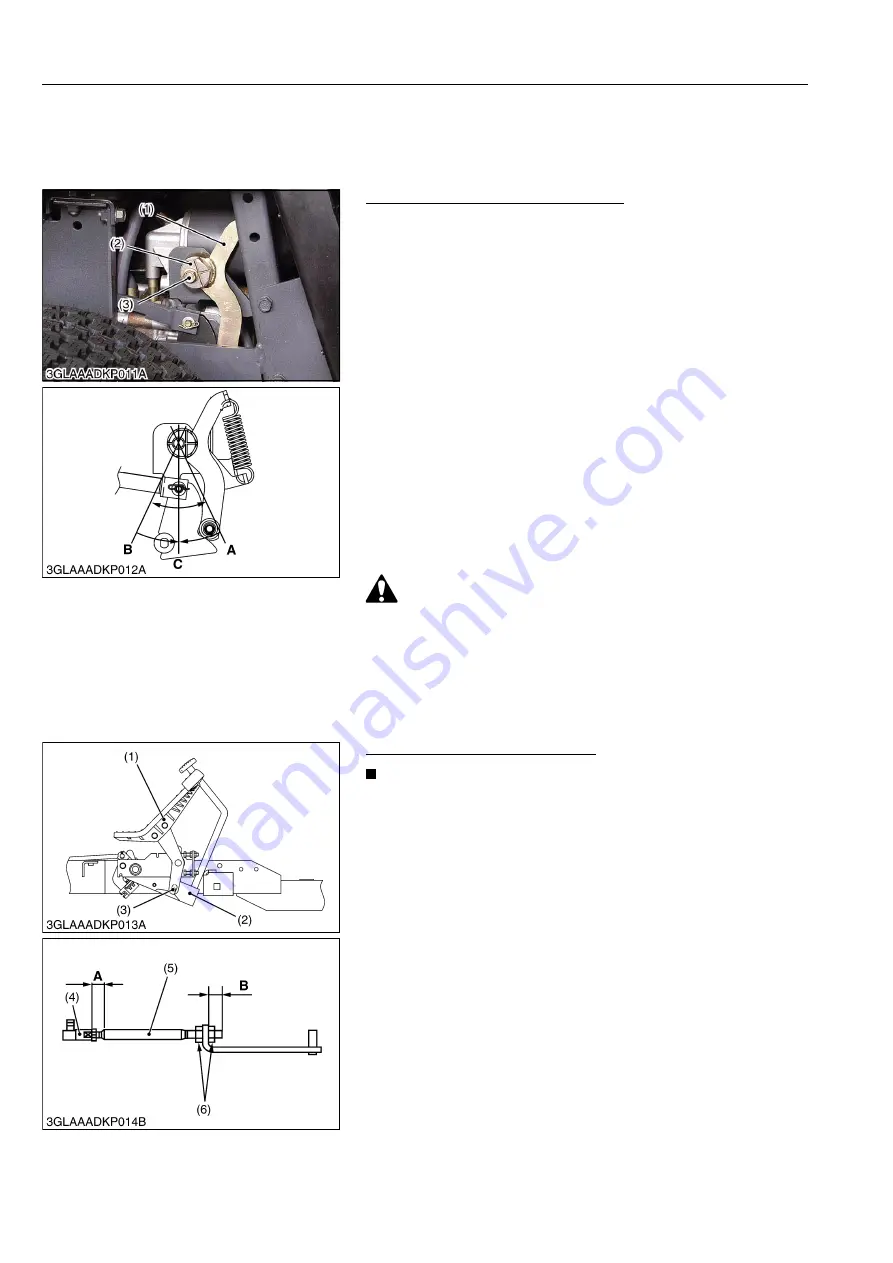
(1) HST Speed Change System
Adjustment of HST Neutral Position
1. Block the front wheels with stoppers, and lift up the rear of
machine with a jack.
2. Remove the left rear wheel.
Remove the cover. [GR1600F, GR1600ID only]
3. Start the engine, and set at approx. 1500 to 3000 min
-1
(rpm).
4. Loosen the holder shaft mounting screw (3).
5. Rotate the holder shaft (2) counterclockwise so that the rear
wheels turn forward.
6. Then rotate it clockwise until the rear wheels stop completely.
7. Put a mark on the neutral arm (1). (Position
B
)
8. Rotate the holder shaft (2) clockwise so that the rear wheels
turn in reverse.
9. Then rotate it counterclockwise until the rear wheels stop
completely.
10. Put a mark on the neutral arm (1). (Position
A
)
11. Set the holder shaft (2) where it is right in the center between
position
A
and
B
and tighten the holder shaft mounting screw
(3) firmly.
This means the hydrostatic transaxle is fully in neutral.
(Position
C
)
WARNING
• Use buddy system in adjusting the neutral position.
• One of you should sit on the operator's seat, adjust the
engine rpm and step on the speed change pedal. The other
should adjust the neutral position.
9Y1210595TXS0014US0
Speed Change Pedal Restriction
NOTE
• You must adjust this after you complete the adjustment of
neutral.
1. Set the speed change pedal (1) to
"NEUTRAL"
position, and
apply the parking brake.
2. Check that the pin (3) of speed change pedal lock with the brake
pedal arm (2).
3. If it is improper, adjust the length
"A"
with the rod end (4) on
speed change rod.
4. Then adjust the length
"B"
with adjusting nut (6) on speed
change rod (5).
(Reference)
• Length
"A"
: 20 mm (0.79 in.)
• Length
"B"
: 16 to 20 mm (0.63 to 0.78 in.)
9Y1210595TXS0015US0
(1) Neutral Arm
(2) Holder Shaft
(3) Holder Shaft Mounting Screw
(1) Speed Change Pedal
(2) Brake Pedal Arm
(3) Pin
(4) Rod End
(5) Speed Change Rod
(6) Adjusting Nut
KiSC issued 11, 2013 A
Содержание GR1600EU
Страница 1: ...GR1600EU WORKSHOP MANUAL KiSC issued 11 2013 A ...
Страница 4: ...I INFORMATION KiSC issued 11 2013 A ...
Страница 10: ...INFORMATION GR1600EU WSM I 5 9Y1210595INI0002US0 KiSC issued 11 2013 A ...
Страница 11: ...INFORMATION GR1600EU WSM I 6 9Y1210595INI0003US0 KiSC issued 11 2013 A ...
Страница 12: ...INFORMATION GR1600EU WSM I 7 9Y1210595INI0007US0 KiSC issued 11 2013 A ...
Страница 15: ...INFORMATION GR1600EU WSM I 10 4 DIMENSIONS 1 GR1600EU GR1600F 9Y1210595INI0005US0 KiSC issued 11 2013 A ...
Страница 16: ...INFORMATION GR1600EU WSM I 11 2 GR1600ID 9Y1210595INI0009US0 KiSC issued 11 2013 A ...
Страница 17: ...G GENERAL KiSC issued 11 2013 A ...
Страница 80: ...1 ENGINE KiSC issued 11 2013 A ...
Страница 138: ...2 TRANSAXLE KiSC issued 11 2013 A ...
Страница 194: ...3 BRAKES KiSC issued 11 2013 A ...
Страница 195: ...CONTENTS 1 BRAKE MECHANISM 3 M1 MECHANISM KiSC issued 11 2013 A ...
Страница 205: ...4 FRONT AXLE KiSC issued 11 2013 A ...
Страница 213: ...5 STEERING KiSC issued 11 2013 A ...
Страница 221: ...6 ELECTRICAL SYSTEM KiSC issued 11 2013 A ...
Страница 223: ...ELECTRICAL SYSTEM GR1600EU WSM 6 M1 1 WIRING DIAGRAM 1 GR1600EU GR1600F KiSC issued 11 2013 A ...
Страница 224: ...ELECTRICAL SYSTEM GR1600EU WSM 6 M2 2 GR1600ID KiSC issued 11 2013 A ...
Страница 257: ...7 MOWER KiSC issued 11 2013 A ...
Страница 260: ...MOWER GR1600EU WSM 7 M2 The mower belt moves in the arrow direction 9Y1210595MOM0003US0 KiSC issued 11 2013 A ...