background image

67

PERIODIC SERVICE

EVERY 2 YEARS

B

Flushing Cooling System and Changing 

Coolant

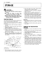
To avoid personal injury:

A

Do not remove radiator cap while coolant is
hot. When cool, slowly rotate cap to the first
stop and allow sufficient time for excess
pressure to escape before removing the cap
completely.

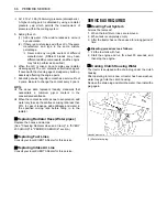
1. Stop the engine, remove the key and let it cool down.
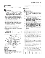
2. To drain the coolant, open the radiator drain cock, and

remove radiator cap. The radiator cap must be
removed to completely drain the coolant.

3. After all coolant is drained, close the drain cock.
4. Fill with clean soft water and cooling system cleaner.
5. Follow directions of the cleaner instruction.
6. After flushing, fill with clean soft water and anti-freeze

until the coolant level is just below the radiator cap. 
Install the radiator cap securely.

7. Fill with coolant up to the "FULL" mark of recovery

tank.

8. Start and operate the engine for few minutes.
9. Stop the engine, remove the key and let cool. 
10.Check coolant level of recovery tank and add coolant

if necessary.

11.Properly dispose of used coolant.

A

Do not start engine without coolant.

A

Use clean, fresh soft water and anti-freeze to fill the
radiator and recovery tank.

A

When mixing the anti-freeze with water, the anti-freeze
mixing ratio is 50 %.

A

Securely tighten radiator cap. If the cap is loose or
improperly fitted, water may leak out and the engine
could overheat.

B

Anti-Freeze

To avoid personal injury:

A

When using antifreeze, put on some protection
such as rubber gloves (Antifreeze contains
poison.).

A

If should drink antifreeze, throw up at once and
take medical attention.

A

When antifreeze comes in contact with the skin
or clothing, wash it off immediately.

A

Do not mix different types of Antifreeze.
The mixture can produce chemical reaction
causing harmful substances.

A

Antifreeze is extremely flammable and
explosive under certain conditions. Keep fire
and children away from antifreeze.

A

When draining fluids from the engine, place
some container underneath the engine body.

A

Do not pour waste onto the grounds, down a
drain, or into any water source.

A

Also, observe the relevant environmental
protection regulations when disposing of
antifreeze.

If it freezes, coolant can damage the cylinders and
radiator. If the ambient temperature falls below 0
(32

) or before a long-term storage, let out cooling water

completely, or mix fresh water with long-life coolant and fill
the radiator and recovery tank with the mixture.
1. Long-life coolant (hereafter LLC) comes in several

types. Use ethylene glycol (EG) type for this engine.

2. Before employing LLC-mixed cooling water, fill the

radiator with fresh water and empty it again. 
Repeat this procedure 2 or 3 times to clean up the
inside.

3. Mixing the LLC 

Put the LLC in cooling water in the percentage (%) for
a target temperature. When mixing, stir it up well, and
then fill into the radiator.

4. The procedure for the mixing of water and antifreeze

differs according to the make of the antifreeze and the
ambient temperature. Refer to SAE J1034 standard,
more specifically also to SAE J814c.

A

When the antifreeze is mixed with water, the
antifreeze mixing ratio must be less than 50%.

Coolant capacity 

(with recovery tank)

3.9 L (4.1 U.S.gals.)

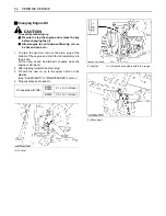
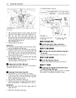
(1) Radiator cap
(2) Recovery tank
(3) Drain cock

(A) "FULL"
(B) "LOW"

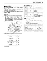
Vol % 

Anti-freeze

Freezing Point

Boiling Point*

40 
50

-24 
-37

-12 
-34

106 
108

222 
226

Содержание B2320

Страница 1: ......

Страница 2: ...vel Roll Over Protective Structures Revolutions Per Minute Revolutions Per Second Society of Automotive Engineers USA Slow Moving Vehicle ABBREVIATION LIST California Proposition 65 The engine exhaust from this product contains chemicals known to the State of California to cause cancer birth defects or other reproductive harm WARNING IMPORTANT The engine in this machine is not equipped by the manu...

Страница 3: ...Diesel Preheat Glow Plugs Low Temperature Start Aid Starter Control Power Take Off Control Off Position Disengaged Power Take Off Control On Position Engaged Differential Lock Position Control Raised Position Position Control Lowered Position Draft Control Shallow Position Draft Control Deep Position 3 Point Lowering Speed Control Remote Cylinder Retract Remote Cylinder Extend Hazard Warning Light...

Страница 4: ...ent or property damage could result if instructions are not followed NOTE Gives helpful information FOREWORD 3 SAFETY FIRST You are now the proud owner of a KUBOTA Tractor This tractor is a product of KUBOTA quality engineering and manufacturing It is made of fine materials and under a rigid quality control system It will give you long satisfactory service To obtain the best use of your tractor pl...

Страница 5: ... the First 50 Hours 17 Changing Lubricating Oil for New Tractors 17 OPERATING FOLDABLE ROPS 17 To Fold the ROPS 17 To Raise the ROPS to Upright Position 18 Adjustment of Foldable ROPS 19 STARTING 19 Operator s Seat 19 Seat Belt 20 Head Light Turn Signal Hazard Light Switch 20 Brake Pedals Right and Left 21 Clutch Pedal 21 Range Gear Shift Lever L M H HST Type 22 Main Gear Shift Lever Range Gear Sh...

Страница 6: ... Top Link Mounting Holes 32 Drawbar 32 Lifting Rod Right 32 Top Link 32 Check Chains 33 DRAWBAR 33 Adjusting Drawbar Length 33 HYDRAULIC UNIT 34 3 POINT HITCH CONTROL SYSTEM 34 Hydraulic Control 34 Position Control 34 Implement Lowering Limit 35 3 point Hitch Lowering Speed 35 AUXILIARY HYDRAULICS 35 Hydraulic Block Type Outlet 35 DUAL REMOTE HYDRAULIC CONTROL SYSTEM if equipped 37 Control Lever a...

Страница 7: ...ating Grease Fittings 54 Checking Engine Start System 55 Checking Wheel Nut Torque 56 EVERY 100 HOURS 57 Battery 57 Cleaning Air Cleaner Primary Element 58 Cleaning Fuel Filter 59 Adjusting Fan Belt Tension 59 Adjusting Clutch Pedal 60 Adjusting Brake Pedal 60 Checking Fuel Line 61 EVERY 200 HOURS 61 Replacing Engine Oil Filter 61 Changing Engine Oil 62 Replacing Transmission Oil Filter HST Type 6...

Страница 8: ...reeze 67 Replacing Radiator Hose Water pipes 68 Replacing Fuel Lines 68 Replacing Intake Air Line 68 SERVICE AS REQUIRED 68 Bleeding Fuel System 68 Draining Clutch Housing Water 68 Replacing Fuse 69 Replacing Light Bulb 69 STORAGE 70 TRACTOR STORAGE 70 REMOVING THE TRACTOR FROM STORAGE 70 TROUBLESHOOTING 71 ENGINE TROUBLESHOOTING 71 OPTIONS 72 ...

Страница 9: ...uctural member of the CAB or ROPS is damaged replace the entire structure at your local KUBOTA Dealer 4 Always use the seat belt if the tractor has a CAB or ROPS Do not use the seat belt if a foldable ROPS is down or there is no ROPS Check the seat belt regularly and replace if frayed or damaged 5 Do not operate tractor or any implement attached to it while under the influence of alcohol medicatio...

Страница 10: ... Never hitch to axle housing or any other point except drawbar such arrangements will increase the risk of serious personal injury or death due to a tractor upset 2 Keep all shields and guards in place Replace any that are missing or damaged 3 Avoid sudden starts To avoid upsets slow down when turning on uneven ground and before stopping 4 The tractor cannot turn with the differential locked and a...

Страница 11: ...ntrol 5 To improve stability on slope set widest wheel tread as shown in TIRE WHEEL AND BALLAST section Follow recommendations for proper ballasting C Driving the tractor on the road 1 Lock the two brake pedals together to help assure straight line stops Uneven braking at road speeds could cause the tractor to tip over 2 Check the front wheel engagement The braking characteristics are different be...

Страница 12: ...he implement lowering speed knob in the LOCK position to hold the implement in the raised position Before servicing the tractor park it on a firm flat and level surface set the parking brake lower all implements to the ground place the gear shift lever in neutral stop the engine and remove the key 1 Allow the tractor time to cool off before working on or near the engine muffler radiator etc 2 Alwa...

Страница 13: ...sure that wheel bolts have been tightened to the specified torque 14 Do not work under any hydraulically supported devices They can settle suddenly leak down or be accidentally lowered If it is necessary to work under tractor or any machine elements for servicing or adjustment securely support them with stands or suitable blocking beforehand 15 Escaping hydraulic fluid under pressure has sufficien...

Страница 14: ...SAFE OPERATION 6 7 DANGER WARNING AND CAUTION LABELS ...

Страница 15: ...7 SAFE OPERATION ...

Страница 16: ...r warning and caution labels with new labels from your local KUBOTA Dealer 4 If a component with danger warning and caution label s affixed is replaced with new part make sure new label s is are attached in the same location s as the replaced component 5 Mount new danger warning and caution labels by applying on a clean dry surface and pressing any bubbles to outside edge 8 CARE OF DANGER WARNING ...

Страница 17: ... to see your KUBOTA Dealer For service contact the KUBOTA Dealership from which you purchased your tractor or your local KUBOTA Dealer When in need of parts be prepared to give your dealer both the tractor and engine serial numbers Locate the serial numbers now and record them in the space provided Type Serial No Tractor Engine Date of Purchase Name of Dealer To be filled in by purchaser 1 Tractor...

Страница 18: ...44 71 52 78 58 Battery 12 V RC 80 min CCA 430 A Capacities Fuel tank L U S gals 26 6 9 Engine crankcase with filter L U S qts 3 1 3 3 3 5 3 7 Engine coolant L U S qts 3 9 4 1 Transmission case L U S gals 14 3 7 15 4 0 Dimensions Overall length without 3P mm in 2360 92 9 2385 93 9 2360 92 9 2385 93 9 2415 95 1 Overall width mm in 900 35 4 1145 45 1 938 36 9 1145 45 1 1245 49 0 Overall height with R...

Страница 19: ...with brake m feet 2 1 6 9 Hydraulic unit Hydraulic control system Position control valve Quarter inching valve Position control valve Quarter inching valve Pump capacity L min gals min 3P 17 9 4 7 Power steering 13 5 3 6 Three point hitch SAE Category 1 Max lift force At lift points kg lbs 750 1655 615 1356 750 1655 615 1356 24 in behind lift point kg lbs 590 1300 480 1058 590 1300 480 1058 PTO Re...

Страница 20: ...to 9 4 0 to 15 1 0 to 9 4 Model B2620 B2920 Tire size Rear 11 2 16 Farm 33 x 12 5 15 Turf Range gear shift lever km h mph km h mph Forward Low 0 to 6 0 0 to 3 7 0 to 5 6 0 to 3 5 Middle 0 to 9 9 0 to 6 2 0 to 9 3 0 to 5 8 High 0 to 20 2 0 to 12 6 0 to 18 9 0 to 11 7 Reverse Low 0 to 4 8 0 to 3 0 0 to 4 5 0 to 2 8 Middle 0 to 7 9 0 to 4 9 0 to 7 4 0 to 4 6 High 0 to 16 1 0 to 10 0 0 to 15 1 0 to 9 ...

Страница 21: ...ry depending on soil operating conditions Tread max width with farm tires Lower link end max loading weight W0 Front Rear B2320DTN 705 mm 27 8 in 750 mm 29 5 in 300 kg 660 lbs B2320HSDN 780 mm 30 7 in 750 mm 29 5 in B2320DT B2320HSD 800 mm 31 5 in 900 mm 35 4 in B2620HSD B2920HSD 815 mm 32 1 in 950 mm 37 4 in Actual figures B2320 B2620 B2920 Implement weight W1 and or size Max Drawbar Load W2 Trai...

Страница 22: ...w Max size cm in 56 22 x 1 Cultivator Max size cm in 122 48 1 Row 137 54 1 Row Disc harrow Max harrowing width cm in Max weight kg lbs 137 54 190 420 152 60 190 420 Sprayer Max tank capacity L U S gals 150 40 190 50 Front blade Max cutting width cm in Sub frame 122 48 Necessary 152 60 Necessary Rear blade Max cutting width cm in Max weight kg lbs 152 60 160 350 Front loader Max lifting capacity kg...

Страница 23: ...nel Switches and Hand Controls ILLUSTRATED CONTENTS 1 Turn signal Hazard light indicator 20 2 Coolant temperature gauge 26 3 Turn signal light switch 20 4 Head light switch 20 5 Hourmeter Tachometer 26 6 Easy Checker TM 25 7 Fuel gauge 26 8 Key switch 12 9 Hazard light switch 20 ...

Страница 24: ... control dial if equipped 6 Differential lock pedal 27 7 Range gear shift lever 22 8 PTO gear shift lever 29 9 Seat belt 20 10 Cup holder 11 Hand throttle lever 23 12 Brake pedal 21 13 Parking brake lever 27 14 Loader lock lever 38 15 Loader control lever 12 37 16 Front wheel drive lever 23 17 Hydraulic control lever Except B2320HSDN 34 Position control lever B2320HSDN 34 18 Operator s seat 19 19 ...

Страница 25: ...ipped 5 Range gear shift lever 22 6 PTO gear shift lever 29 7 Seat belt 20 8 Cup holder 9 Hand throttle lever 23 10 Brake pedal 21 11 Parking brake lever 27 12 Foot throttle 23 13 Loader lock lever if equipped 38 14 Loader control lever if equipped 12 37 15 Main gear shift lever 22 16 Front wheel drive lever 23 17 Hydraulic control lever Except B2320DTN 34 Position control lever B2320DTN 34 18 Ope...

Страница 26: ...T type Manual transmission type 1 Clutch pedal 2 Brake pedal left 3 Brake pedal right 4 Brake pedal lock 5 Speed control pedal forward 6 Speed control pedal reverse 7 Differential lock pedal 1 Clutch pedal 2 Brake pedal left 3 Brake pedal right 4 Brake pedal lock 5 Differential lock pedal 6 Foot throttle ...

Страница 27: ...brake ON and implement lowered to the ground Check item Walk around inspection Check engine oil level Check transmission oil level Check coolant level Clean grill and radiator screen Check air cleaner evacuator valve When used in a dusty place Check brake and clutch pedal Check indicators gauges and meter Check lights Check seat belt and ROPS Refuel See DAILY CHECK in PERIODIC SERVICE section Care...

Страница 28: ... use starting fluid or ether A To protect the battery and the starter make sure that the starter is not continuously turned for more than 30 seconds STARTING THE ENGINE 1 To set the parking brake 1 Interlock the brake pedals 2 Depress the brake pedals 3 Latch the brake pedals with the parking brake lever 2 To release the parking brake depress the brake pedals again A The PTO gear shift lever shift...

Страница 29: ...osition 1 Range gear shift lever L M H 2 Speed set lever 3 Speed control pedal A OFF B ON H HIGH M MIDDLE L LOW N NEUTRAL POSITION Manual Transmission Type Place the main gear shift lever in NEUTRAL position 1 Main gear shift lever 4 Lock the loader control lever in NEUTRAL position if equipped 1 Loader control lever 2 Lock lever A LOCK 5 Except B2320DTN B2320HSDN Place the hydraulic control lever...

Страница 30: ...Never fail to conduct physical daily checks carefully by referring to DAILY CHECK section See DAILY CHECK in PERIODIC SERVICE section B2320DTN B2320HSDN Place the position control lever in LOWEST position 1 Position control lever A DOWN 6 Set the throttle lever to about 1 2 way 1 Hand throttle lever A INCREASE B DECREASE 7 Insert the key into the key switch and turn it ON A OFF B ON C PREHEAT D ST...

Страница 31: ...lever in OFF position during warm up For five minutes after engine start up allow engine to warm up without applying any load this is to allow oil to reach every engine part If load should be applied to the engine without this warm up period trouble such as seizure breakage or premature wear may develop BWarm up Transmission Oil at Low Ambient Temperatures Hydraulic oil serves as transmission flui...

Страница 32: ... 6 Attach the red clamp to the positive red or pos terminal of the dead battery and clamp the other end of the same cable to the positive red or pos terminal of the helper battery 7 Clamp the other cable to the negative black or neg terminal of the helper battery 8 Clamp the other end to the engine block or frame of the disabled tractor as far from the dead battery as possible 9 Start the helper v...

Страница 33: ...uitable speeds Do not operate the tractor at fast speed The above precautions are not limited only to new tractors but to all tractors But it should be especially observed in the case of new tractors BChanging Lubricating Oil for New Tractors The lubricating oil is especially important in the case of a new tractor The various parts are not broken in and are not accustomed to each other small metal...

Страница 34: ...secured with the hair pins BTo Raise the ROPS to Upright Position 1 Remove both hair pins and set pins 2 Raise ROPS to the upright position To avoid personal injury A Raise the ROPS slowly and carefully 3 Insert both set pins and secure them with the hair pins To avoid personal injury A Make sure that both set pins are properly installed as soon as the ROPS is in the upright position and secured w...

Страница 35: ...A Make sure that the seat is completely secured after each adjustment A Do not allow any person other than the driver to ride on the tractor C Position adjustment Pull in the position adjust lever and slide the seat backward or forward as required The seat will lock in position when the lever is released A After adjusting the operator s seat be sure to check that the seat is properly locked 1 Nut ...

Страница 36: ...t or right turn signal is activated in combination with the hazard lights the indicated turning light will flash and the other will stay on C Turn Signal with Hazard Light Switch Off 1 To indicate a right turn without hazard lights hazard switch off turn the turn signal switch clockwise 2 To indicate a left turn without hazard lights turn the turn signal switch counterclockwise 3 When the left or ...

Страница 37: ...ng the parking brake be sure to interlock the right and left pedals as illustrated below 2 Use individual brakes to assist in making sharp turns at slow speeds Field Operation Only Disengage the brake pedal lock and depress only one brake pedal 3 Be sure brake pedals have equal adjustment when using locked together BClutch Pedal To avoid personal injury A Sudden release of the clutch may cause the...

Страница 38: ...ansmission 3 Release the speed control pedal to neutral position 4 Depress the clutch pedal and then shift the range gear shift lever BMain Gear Shift Lever Range Gear Shift Lever L M H Manual Transmission Type The main gear shift lever pattern is in the form of an H The range gear shift lever moves in the form of an I in 3 stages HIGH MIDDLE and LOW By combination of using the main gear shift lev...

Страница 39: ...wear quickly if front wheel drive is engaged on paved roads C Front wheel drive is effective for the following jobs 1 When greater pulling force is needed such as working in a wet field when pulling a trailer or when working with a front end loader 2 When working in sandy soil 3 When working on a hard soil where a rotary tiller might push the tractor forward 4 Additional braking at reduced speeds ...

Страница 40: ...l KUBOTA Dealer Forward Pedal Depress the forward pedal with the toe of your right foot to move forward Reverse Pedal Depress the reverse pedal with the heel of your right foot to move backward A To prevent the damage of speed set device do not depress the reverse pedal when the speed set device is engaged 8 Unlock the parking brake and slowly release the clutch 1 Brake pedals 9 Depress the speed ...

Страница 41: ...e engine will stop regardless of whether the machine is moving or not This is because the tractor is equipped with Operator Presence Control system OPC STOPPING BStopping 1 Slow the engine down 2 Step on the clutch and brake pedal 3 After the tractor has stopped disengage the PTO lower the implement to the ground shift the transmission to neutral release the clutch pedal and set the parking brake ...

Страница 42: ...ndicates the temperature of the coolant C for cold and H for hot 2 If the indicator reaches the H position red zone engine coolant is overheated Check the tractor by referring to TROUBLESHOOTING section BHourmeter Tachometer This meter gives readings for engine speed PTO shaft speed and the hours the tractor has been operated 1 The tachometer indicates the engine speed and the 540 PTO shaft speed ...

Страница 43: ... park on an incline be sure to chock the wheels to prevent accidental rolling of the machine OPERATING TECHNIQUES BDifferential Lock To avoid personal injury due to loss of steering control A Do not operate the tractor at high speed with differential lock engaged A Do not attempt to turn with the differential lock engaged A Be sure to release the differential lock before making a turn in field con...

Страница 44: ... forward could cause the tractor to tip over backward Stay off hills and slopes too steep for safe operation A Avoid changing gears when climbing or descending a slope A If operating on a slope never disengage the clutch or shift levers to neutral Doing so could cause loss of control A Do not drive the tractor close to the edges of ditches or banks which may collapse under the weight of the tracto...

Страница 45: ...s to the PTO reduce engine speed when engaging the PTO then open the throttle to the recommended speed A To avoid damage of transmission do not shift PTO gear shift lever until the PTO has stopped completely C Mid PTO Except B2320DTN The mid PTO is available for KUBOTA approved implements C Rear PTO speed C Mid PTO speed Except B2320DTN A There is a PTO 1 540rpm indicator mark on the tachometer fa...

Страница 46: ...ng steps 1 Apply the parking brakes and place blocks at the tires 2 Make sure the shift levers are at NEUTRAL and start the engine 3 Set the PTO gear shift lever to Rear PTO 1st position 4 Set the engine speed to provide recommended rear PTO speed 5 Dismount the seat and tilt up quickly engine will stop if there is a delay in tilting up the seat A If the PTO system is engaged and you stand up from...

Страница 47: ...31 THREE POINT HITCH DRAWBAR THREE POINT HITCH DRAWBAR 1 Top link 2 Lifting rod Left 3 Check chains 4 Turnbuckle 5 Lower link 6 Drawbar 7 Lifting rod Right 8 Top link holder ...

Страница 48: ...ake is applied A Before attaching or detaching implement locate the tractor and implement on a firm flat and level surface A Whenever an implement or other attachment is connected to the tractor 3 point hitch check full range of operation for interference binding or PTO driveline separation BLifting Rod Right Level a 3 point mounted implement from side to side by turning the adjusting handle to sh...

Страница 49: ...y A Never pull from the top link the rear axle or any point above the drawbar Doing so could cause the tractor to tip over rearward causing personal injury or death BAdjusting Drawbar Length When towing an implement use of B hole in drawbar is recommended The acceptable drawbar load is provided in the IMPLEMENT LIMITATIONS section 1 Turnbuckle 2 Snap pin 1 PTO shaft 2 Drawbar 3 Drawbar pin Holes A...

Страница 50: ...3 point hitch mounted implement regardless of the amount of pull required A If the 3 point hitch can not be raised by setting the hydraulic control lever to the UP position after long term storage or when changing the transmission oil turn steering wheel to the right and left several times to bleed air from the system A Do not operate until the engine is warmed up If operation is attempted when th...

Страница 51: ...CS Hydraulic outlet is provided on the tractor without loader valve only BHydraulic Block Type Outlet Hydraulic block type outlet is useful when adding hydraulically operated equipment such as front end loader front blade etc When implement is attached 1 Remove the block cover 2 Attach the block outlet cover option B2320DT A For hydraulic block type outlet be sure to use the control valve of the P...

Страница 52: ...ded on the tractor A If the implement control valve has a relief valve the tank port flow from implement should be connected to the port located on the right hand side of transmission case 1 Return port 1 Block cover 2 Block outlet cover option 3 Outlet 4 Inlet A To implement inlet Max flow 16 6 L min 4 4 U S gals min Max pressure 13 2 to 13 7 Mpa 135 to 140 kgf cm 1920 to 1992 psi B From implemen...

Страница 53: ... connections when using this valve to take off hydraulic power for the hydraulic cylinder BLoader Remote Control Valve Lever 1 Before moving the lever make sure that the hydraulic hoses for attachments are connected 2 Move the lever diagonally a b c shown in the figure and the first and second segments can be controlled at once A Move the lever to the FLOAT position and it will be held there by th...

Страница 54: ... valve lock is to prevent accidental actuation when implement is not in use or during transport The control valve is equipped with a valve lock feature The control valve is locked in NEUTRAL position The lock is not intended and will not prevent a leak down of the implement during the period of storage 1 Lock lever A LOCK B UNLOCK ...

Страница 55: ...ly when there is some obstacle thatprevents you from using the standard Hydraulic control Except B2320 DTN B2320HSDN Position control B2320DTN B2320HSDN YES NO Loose Adjust the check chains so that the implement can move 5 to 6cm 2 0 to 2 4 in laterally For implements with gauge wheels lower the implements to the ground Disc plow Harrower spike springtooth disc type Sub soiler Weeder ridger YES Ti...

Страница 56: ...ot work under any hydraulically supported devices They can settle suddenly leak down or be accidentally lowered If necessary to work under tractor or any machine elements for servicing or adjustment securely support them with stands or suitable blocking beforehand A Never operate tractor with a loose rim wheel or axle BFront Wheels Front tread width can not be adjusted A Do not turn front discs to...

Страница 57: ...rm B2320 HSDN B2320 DTN 6 12 Farm B2320 HSDN B2320 DTN B2320 7 12 Farm B2620 B2920 23x8 50 12 Turf B2320 B2620 B2920 21x8 00 10 Bar B2320 B2620 B2920 23x8 50 12 Ind B2320 B2620 B2920 Tire Models Tread 6 12 Farm B2320 7 12 Farm B2620 B2920 22x8 50 12 Turf B2320 24x8 50 12 Turf B2620 B2920 ...

Страница 58: ...lustrated transmission parts may be damaged A When re fitting or adjusting a wheel tighten the bolts to the following torques then recheck after driving the tractor forward and backward for 5 minutes and thereafter on a daily basis A Insert the bolt from the indented side of the cotter C as shown Tire Models Tread 8 16 Farm B2320 HSDN B2320 DTN 8 3 16 Farm B2320 HSDN B2320 DTN 1 Nut 2 Spring washe...

Страница 59: ... models C Except USA models Tire Models Tread 9 5 16 Farm B2320 11 2 16 Farm B2620 B2920 33x 12 5 15 Turf B2320 B2620 B2920 31x 15 5 15 Bar B2320 B2620 B2920 12 16 5 Ind B2320 B2620 B2920 Tire Models Tread 9 5 16 Farm B2320 9 5 18 Farm B2620 B2920 31x 13 5 15 Turf B2320 315 75D 15 Turf B2620 B2920 ...

Страница 60: ...nt wheels with liquid BFront Ballast Add weights if needed for stability and improving traction Heavy pulling and heavy rear mounted implements tend to lift front wheels Add enough ballast to maintain steering control and prevent tip over Remove weight when no longer needed C Front End Weights option The front end weights can be attached to the bumper See your implement operator s manual for requi...

Страница 61: ...HSDN Add weight to rear wheels if needed to improve traction or for stability The amount of rear ballast should be matched to job and the ballast should be removed when it is not needed The weight should be added to the tractor in the form of liquid ballast rear wheel weight or a combination of both for B2320 narrow tractors only The rear wheel weights can be attached to the rear wheels for increa...

Страница 62: ...nt Primary element Clean every 100 Hr 58 1 Replace every 1 year 66 2 Secondary element Replace every 1 year 66 13 Fuel filter element Check every 100 Hr 59 Replace every 400 Hr 66 14 Fan belt Adjust every 100 Hr 59 15 Clutch Adjust every 100 Hr 60 16 Brake Adjust every 100 Hr 60 17 Radiator hose and clamp Check every 200 Hr 64 Replace every 2 years 68 18 Fuel line Check every 100 Hr 61 Replace eve...

Страница 63: ...original transmission hydraulic fluid No Locations Capacities Lubricants B2320DTN B2320DT B2320HSDN B2320HSD B2620HSD B2920HSD 1 Fuel 26 L 6 9 U S gals No 2 D diesel fuel No 1 D diesel fuel if temperature is below 10 14 2 Coolant with recovery tank 3 9 L 4 1 U S qts Fresh clean soft water with anti freeze 3 Engine crankcase with filter 3 1 L 3 3 U S qts 3 5 L 3 7 U S qts Engine oil Refer to next p...

Страница 64: ... 2 D or use No 1 D S500 or S15 diesel fuel as an alternative to No 1 D if outside air temperature is below 10 14 C Transmission Oil The oil used to lubricate the transmission is also used as hydraulic fluid To insure proper operation of the hydraulic system and to complete lubrication of the transmission it is important that a multi grade transmission fluid is used in this system We recommend the ...

Страница 65: ...act with moving parts A Never open the hood or engine side cover while the engine is running A Do not touch muffler or exhaust pipes while they are hot Severe burns could result A Support hood with other hand while unlocking support rod BHood To open the hood twist the mascot to release the latch and open the hood A To close the hood hold the hood and release the support rod BFront Grille To remov...

Страница 66: ...ervice life of the machine make a thorough daily inspection before operating the machine to start the engine To avoid personal injury A Be sure to check and service the tractor on a level surface with the engine shut off and the parking brake ON and implement lowered to the ground BWalk Around Inspection Look around and under the tractor for such items as loose bolts trash build up oil or coolant ...

Страница 67: ...k before parking overnight BChecking Engine Oil Level To avoid personal injury A Be sure to stop the engine before checking the oil level 1 Park the machine on a flat surface 2 Check engine oil before starting the engine or 5 minutes or more after the engine has stopped 3 To check the oil level draw out the dipstick wipe it clean replace it and draw it out again Check to see that the oil level lie...

Страница 68: ... and allow sufficient time for excess pressure to escape before removing the cap completely 1 Check to see that the coolant level is between the FULL and LOW marks of recovery tank 2 When the coolant level drops due to evaporation add soft water only up to the full level In case of leakage add anti freeze and soft water in the specified mixing ratio up to the full level See Flushing Cooling System...

Страница 69: ...nt of radiator completely BChecking Brake Pedals and Clutch Pedal 1 Inspect the brake and clutch pedals for free travel and smooth operation 2 Adjust if incorrect measurement is found See Adjusting Clutch Pedal and Adjusting Brake Pedal in EVERY 100 HOURS in PERIODIC SERVICE section A Brake pedals should be equal when depressed BChecking Gauges Meter and Easy Checker TM 1 Inspect the instrument pa...

Страница 70: ...ectly to battery wiring connectors electrical components or instrument panel Inspect the following Regularly 1 Check wiring for chafed or cracked insulation 2 Check wiring harness clamps Replace if necessary 3 Check connectors and terminals for looseness contamination or overheated discolored connections 4 Check instrument panel for correct operation of switches and gauges Consult your KUBOTA Deal...

Страница 71: ...tion 4 The engine must not crank C Test Switch for the PTO gear shift lever 1 Fully depress the clutch pedal 2 Shift the main gear shift lever to NEUTRAL position 3 Shift the PTO gear shift lever to ON Engaged position 4 Turn the key to START position 5 The engine must not crank C Test Switch for the Operator s seat 1 Sit on operator s seat 2 Start the engine 3 Fully depress the clutch pedal 4 Shi...

Страница 72: ...depress the clutch pedal 4 Shift the PTO gear shift lever to ON Engaged position 5 Stand up Do not get off the machine 6 The engine must shut off after approximately 1 second 7 If it does not stop consult your local KUBOTA Dealer for this service A If the engine cranks during any of these tests consult your local KUBOTA Dealer to have unit checked before operating BChecking Wheel Nut Torque To avo...

Страница 73: ...ome servicing If the battery is weak the engine will be difficult to start and the lights will be dim It is important to check the battery periodically C How to read the indicator Check the battery condition by reading the indicator C Battery Charging To avoid personal injury A When the battery is being activated hydrogen and oxygen gases in the battery are extremely explosive Keep open sparks and...

Страница 74: ...m the inside turning the element Pressure of compressed air must be under 205 kPa 2 1 kgf cm 30 psi 2 When carbon or oil adheres to the element soak the element in detergent for 15 minutes then wash it several times in water rinse with clean water and dry it naturally After element is fully dried inspect inside of the element with a light and check if it is damaged or not 3 Replace air cleaner pri...

Страница 75: ...half full A If dust dirt or water enters the fuel system the fuel pump and injection nozzles are subject to premature wear To prevent this be sure to clean the fuel filter bowl and element periodically BAdjusting Fan Belt Tension 1 Stop the engine and remove the key 2 Apply moderate thumb pressure to belt between pulleys 3 If tension is incorrect loosen the alternator mounting bolts and using a le...

Страница 76: ... the wheels before checking brake pedal 1 Release the parking brake 2 Slightly depress the brake pedals and measure free travel at the top of pedal stroke 3 If adjustment is needed loosen the lock nut and turn the turnbuckle to adjust the rod length within acceptable limits 4 Retighten the lock nut Proper clutch pedal free travel 20 to 30 mm 0 8 to 1 2 in on the pedal 1 Lock nut 2 Turnbuckle A FRE...

Страница 77: ...llow engine to cool down sufficiently oil can be hot and can burn 1 Remove the oil filter 2 Put a film of clean engine oil on the rubber seal of the new filter 3 Tighten the filter quickly until it contacts the mounting surface Tighten filter by hand an additional 1 2 turn only 4 After the new filter has been replaced the engine oil normally decreases a little Make sure that the engine oil does no...

Страница 78: ...m of the engine and drain the oil completely into the oil pan All the used oil can be drained out easily when the engine is still warm 2 After draining reinstall the drain plug 3 Fill with the new oil up to the upper notch on the dipstick See LUBRICANTS in MAINTENANCE section 4 Properly dispose of used oil Oil capacity with filter B2320 B2620 3 1 L 3 3 U S qts B2920 3 5 L 3 7 U S qts 1 Oil inlet 1...

Страница 79: ...w filter 5 Quickly tighten the filter until it contacts the mounting surface then with a filter wrench tighten it an additional 1 turn only 6 After the new filter has been replaced fill the transmission oil up to the upper notch on the dipstick 7 After running the engine for a few minutes stop the engine and check the oil level again add oil to the prescribed level 8 Make sure that the transmissio...

Страница 80: ... away from the machine for further 10 minutes or while the steam blows out 4 Check that there are no dangers such as burns Get rid of the causes of overheating according to the manual see TROUBLESHOOTING section and then start again the engine BChecking Intake Air Line 1 Check to see that hoses and hose clamps are tight and not damaged 2 If hoses and clamps are found worn or damaged replace or rep...

Страница 81: ...B2320DTN 3 Remove the oil filter 4 Put a film of clean transmission oil on rubber seal of new filter 5 Tighten the filter quickly until it contacts the mounting surface Tighten filter by hand an additional 1 2 turn only 6 Fill with new KUBOTA SUPER UDT fluid up to the upper notch on the dipstick See LUBRICANTS in MAINTENANCE section and Checking Transmission Fluid Level in DAILY CHECK in PERIODIC ...

Страница 82: ...ction BChanging Front Axle Case Oil 1 Park the tractor on a firm flat and level surface 2 To drain the used oil remove the right and left drain plugs and filling plug at the front axle case and drain the oil completely into the oil pan 3 After draining reinstall the drain plugs 4 Fill with new oil up to the upper notch on the dipstick See LUBRICANTS in MAINTENANCE section A After ten minutes check...

Страница 83: ... and take medical attention A When antifreeze comes in contact with the skin or clothing wash it off immediately A Do not mix different types of Antifreeze The mixture can produce chemical reaction causing harmful substances A Antifreeze is extremely flammable and explosive under certain conditions Keep fire and children away from antifreeze A When draining fluids from the engine place some contai...

Страница 84: ...ntrated antifreeze A When the coolant level drops due to evaporation add water only to keep the antifreeze mixing ratio less than 50 In case of leakage add antifreeze and water in the specified mixing ratio before filling in to the radiator BReplacing Radiator Hose Water pipes Replace the hoses and clamps See Checking Radiator Hose and Clamp in EVERY 200 HOURS in PERIODIC SERVICE section BReplacin...

Страница 85: ... electrical system Refer to the TROUBLESHOOTING section of this manual or your local KUBOTA Dealer for specific information dealing with electrical problems C Protected circuit BReplacing Light Bulb 1 Head light Take the bulb out of the light body and replace with a new one 2 Other lights Detach the lens and replace the bulb FUSE No CAPACITY A Protected circuit 1 10 HAZARD 2 30 SOLENOID 3 5 KEY ST...

Страница 86: ...ery in EVERY 100 HOURS in PERIODIC SERVICE section 9 Keep the tractor in a dry place where the tractor is sheltered from the elements Cover the tractor 10 Store the tractor indoors in a dry area that is protected from sunlight and excessive heat If the tractor must be stored outdoors cover it with a waterproof tarpaulin Jack the tractor up and place blocks under the front and rear axles so that al...

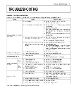
Страница 87: ...r always remove the battery from the engine charge and store it indoors Install it on the tractor only when the tractor is going to be used Insufficient engine power A Insufficient or dirty fuel A The air cleaner is clogged A Check the fuel system A Clean or replace the element Engine stops suddenly A Insufficient fuel A Refuel A Bleed the fuel system if necessary Exhaust fumes are colored Black A...

Страница 88: ... KUBOTA Dealer for further detail A Rear Work Light High visibility for night work A Front end weights For front ballast A Mounting Kit Front end weights To mount Front end weights A Engine Block Heater For extremely cold weather starting ...

Отзывы: