background image

12

SERVICE WORK ON THE CHASSIS

45

12.4

Cleaning the dust boots of the fork legs

Preparatory work

Raise the motorcycle with the lift stand. (

p. 44)

Dismount the front fender. (

p. 54)

601335-10

Main work

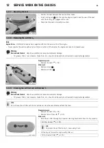
Push dust boots

of both fork legs downward.

Info

The dust boots remove dust and coarse dirt particles from the inside fork
tubes. Over time, dirt can accumulate behind the dust boots. If this dirt is
not removed, the oil seals behind can start to leak.

Warning

Danger of accidents

Reduced braking efficiency due to oil or grease on the

brake discs.

Always keep the brake discs free of oil and grease, and clean them with
brake cleaner when necessary.

Clean and oil the dust boots and inner fork tube of both fork legs.

Universal oil spray (

p. 126)

Press the dust boots back into their normal position.

Remove excess oil.

Finishing work

Install the front fender. (

p. 54)

Remove the motorcycle from the lift stand. (

p. 44)

12.5

Removing the fork legs

Preparatory work

Raise the motorcycle with the lift stand. (

p. 44)

Remove the front wheel.

(

p. 78)

Dismount the front fender. (

p. 54)

Remove the trim. (

p. 66)

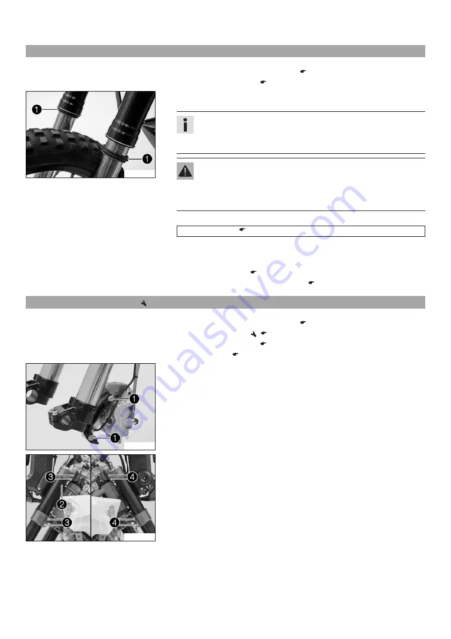
L02727-10

Main work

Remove screws

with washers.

Allow the brake caliper and brake line to hang tension-free to the side.

L02729-10

Remove cable binder

.

Loosen screws

. Take out the left fork leg.

Loosen screws

. Take out the right fork leg.

Содержание 2015 450 Rally Factory Replica

Страница 1: ...OWNER S MANUAL 2015 450 Rally Factory Replica Art no 3213181en ...

Страница 2: ......

Страница 3: ...e technical specifications prices colors forms materials services designs equipment etc without prior notice and without specifying reasons to adapt these to local conditions as well as to stop production of a particular model without prior notice KTM accepts no liability for delivery options deviations from illustrations and descriptions misprints and other errors The models portrayed partly cont...

Страница 4: ...O odometer 25 7 16 Display mode SPEED TR1 trip master 1 25 7 17 Display mode SPEED TR2 trip master 2 25 7 18 Setting TR2 trip master 2 25 7 19 Display mode SPEED A1 average speed 1 26 7 20 Display mode SPEED A2 average speed 2 26 7 21 Display mode SPEED S1 stop watch 1 27 7 22 Display mode SPEED S2 stop watch 2 27 7 23 Table of functions 27 7 24 Table of conditions and menu activation 28 8 PREPARI...

Страница 5: ...l of the foot brake lever 73 13 9 Adjusting the free travel of the foot brake lever 74 13 10 Checking the rear brake fluid level 74 13 11 Adding rear brake fluid 75 13 12 Checking the rear brake linings 75 13 13 Changing the rear brake linings 76 14 WHEELS TIRES 78 14 1 Removing the front wheel 78 14 2 Mounting the front wheel 78 14 3 Removing the rear wheel 79 14 4 Installing the rear wheel 80 14...

Страница 6: ...TABLE OF CONTENTS 4 26 AUXILIARY SUBSTANCES 125 27 STANDARDS 127 INDEX 128 ...

Страница 7: ...standing In the interest of your own safety have these jobs performed by an authorized KTM workshop There your motorcycle will be opti mally cared for by specially trained experts using the specialist tools required Indicates a page reference more information is provided on the specified page 1 2 Formats used The typographical formats used in this document are explained below Specific name Identif...

Страница 8: ...ken Warning Indicates a danger that is likely to lead to fatal or serious injury if the appropriate measures are not taken Caution Indicates a danger that may lead to minor injuries if the appropriate measures are not taken Note Indicates a danger that will lead to considerable machine and material damage if the appropriate measures are not taken Warning Indicates a danger that will lead to enviro...

Страница 9: ... contained in the vehicle but can be ordered under the number in paren theses E g bearing puller 15112017000 During assembly non reusable parts e g self locking screws and nuts seals and seal rings O rings pins lock washers must be replaced by new parts In some instances a thread locker e g Loctite is required The manufacturer instructions for use must be followed After disassembly clean the parts...

Страница 10: ...M PowerParts for your vehicle can be found on the KTM website International KTM Website http www ktm com 3 4 Service A prerequisite for perfect operation and prevention of premature wear is that the service care and tuning work on the engine and chassis is properly carried out as described in the Owner s Manual Incorrect adjustment and tuning of the engine and chassis can lead to damage and breaka...

Страница 11: ...4 VIEW OF VEHICLE 9 4 1 View of vehicle front left L02700 10 1 Clutch lever p 13 2 Seat release strap 3 Shift lever p 17 4 Side stand p 18 ...

Страница 12: ... right L02701 10 1 Kill switch p 13 1 Light switch p 13 1 Turn signal switch p 14 1 Horn button p 14 2 Fuel pump switch p 15 3 Electric starter button p 14 4 Throttle grip p 13 5 Speedometer overview 6 Hand brake lever p 13 7 Foot brake lever p 17 ...

Страница 13: ...s fixed to the right of the steering head 5 3 Engine number 401949 10 The engine number is stamped on the left side of the engine under the engine sprocket 5 4 Key number 402247 10 The key number for the steering lock is stamped onto the key connector 5 5 Fork part number 401947 10 The fork part number is stamped on the inner side of the fork stub ...

Страница 14: ...5 SERIAL NUMBERS 12 5 6 Shock absorber part number 0 0 1 1 401948 10 Shock absorber article number is located on the bottom of the shock absorber com pensating tank ...

Страница 15: ...Possible states Kill switch in basic position In this position the ignition circuit is closed and the engine can be started Kill switch pressed In this position the ignition circuit is interrupted a run ning engine stops and a non running engine will not start 6 5 Light switch L02713 11 The light switch is fitted on the left side of the handlebar Possible states Light off Light switch is turned to...

Страница 16: ...n the right side of the handlebar Possible states Electric starter button in basic position Electric starter button pressed In this position the electric starter is actuated 6 9 Indicator lamp overview L02707 01 Possible states The left low fuel warning lamp lights up orange The fuel level of the two front fuel tanks has reached the reserve mark The oil pressure warning lamp lights up red The oil ...

Страница 17: ...r Fire hazard Fuel is highly flammable Never refuel the vehicle near open flames or burning cigarettes and always switch off the engine first Be careful that no fuel is spilt especially on hot vehicle components Clean up spilt fuel immediately The fuel in the fuel tank expands when warm and may emerge if overfilled Follow the instructions on refueling Warning Danger of poisoning Fuel is poisonous ...

Страница 18: ...10 Turn filler caps and counterclockwise and lift off 6 13 Closing the filler caps L02714 11 Mount filler caps and and turn clockwise until the fuel tanks are tightly closed Info Route fuel tank breather hoses without kinks ...

Страница 19: ...idle speed during a cold start Possible states RPM increase activated Idle speed adjusting screw is pulled out all the way RPM increase deactivated Idle speed adjusting screw is pushed in all the way 6 15 Shift lever 401950 10 The shift lever is mounted on the left side of the engine 401950 11 The gear positions can be seen in the photograph The neutral or idle position is between the first and se...

Страница 20: ...ering head The steering lock is used to lock the steering Steering and therefore riding is no longer possible 6 19 Locking the steering Note Danger of damage The parked vehicle may roll away or fall over Always place the vehicle on a firm and even surface 400732 01 Park the vehicle Turn the handlebar as far as possible to the right Insert the key in the steering lock turn it to the left press it i...

Страница 21: ... Unlocking the steering 400731 01 Insert the key in the steering lock turn it to the left pull it out and turn it to the right Remove the key You can now steer the bike again Info Never leave the key in the steering lock ...

Страница 22: ...umference of the 21 front wheel with stan dard tires The display then changes to the last selected mode 7 3 Kilometers or miles setting Info If you change the unit the value ODO is retained and converted accordingly The values TR1 TR2 A1 A2 and S1 are cleared when the unit of measure is changed Condition The motorcycle is stationary 400329 01 Repeatedly press the button briefly until H appears at ...

Страница 23: ... symbol continues to appear in the display and the next function appears Deactivating a function Press the button The symbol disappears in the display and the next function appears 7 5 Setting the clock Condition The motorcycle is stationary 400330 01 Repeatedly press the button briefly until CLK appears at the bottom right of the display Press the button for 2 3 seconds The hour display flashes S...

Страница 24: ...ition The motorcycle is stationary Repeatedly press the button briefly until H appears at the bottom right of the display In display mode H the service hours of the engine are displayed The service hour counter stores the total traveling time Info The service hour counter is necessary for ensuring that service work is carried out at the right intervals If the speedometer is in H display mode at th...

Страница 25: ...m h Mph flashes In measurement unit mode you can change the unit of measurement Info If no button is pressed for 5 seconds the settings are automatically stored Briefly press the button Starts selection activates Km h display Press the button for 2 3 seconds No function Briefly press the button Activates Mph display Press the button for 2 3 seconds No function Wait 3 5 seconds Changes to the next ...

Страница 26: ... timed with the stop watch Info If the lap time continues running after the button is pressed 9 memory loca tions are occupied Lap 10 must be timed using the button Press the button for 2 3 seconds The stop watch and the lap time are reset Briefly press the button Next display mode Press the button for 2 3 seconds Stops the clock Briefly press the button Starts the stop watch or stop the current l...

Страница 27: ...cally reset to 0 0 Press the button for 2 3 seconds Displays of TR1 A1 and S1 are reset to 0 0 Briefly press the button Next display mode Press the button for 2 3 seconds No function Briefly press the button No function 7 17 Display mode SPEED TR2 trip master 2 400324 01 Repeatedly press the button briefly until TR2 appears at the top right of the dis play TR2 trip master 2 runs constantly and cou...

Страница 28: ...atch 1 The calculation of this value is activated by the first impulse of the wheel speed sensor and ends 3 seconds after the last impulse Press the button for 2 3 seconds Displays of TR1 A1 and S1 are reset to 0 0 Briefly press the button Next display mode Press the button for 2 3 seconds No function Briefly press the button No function 7 20 Display mode SPEED A2 average speed 2 400326 01 Repeate...

Страница 29: ...y mode Press the button for 2 3 seconds No function Briefly press the button Starts or stops S2 7 23 Table of functions Display Press the but ton for 2 3 seconds Briefly press the button Press the but ton for 2 3 seconds Briefly press the button Wait 3 5 sec onds Wait 10 12 sec onds Display mode SPEED H service hours The display changes to the Setup menu of the speedome ter functions Next display ...

Страница 30: ... 2 Increases value of TR2 Increases value of TR2 Reduces value of TR2 Reduces value of TR2 Saves and closes the Setup menu Display mode SPEED A1 average speed 1 Displays of TR1 A1 and S1 are reset to 0 0 Next display mode No function No function Display mode SPEED A2 average speed 2 No function Next display mode No function No function Display mode SPEED S1 stop watch 1 Displays of TR1 A1 and S1 a...

Страница 31: ... are not braking Warning Danger of accidents Unstable riding behavior Do not exceed the maximum permissible weight and axle loads Warning Risk of misappropriation Usage by unauthorized persons Never leave the vehicle while the engine is running Secure the vehicle against use by unauthorized persons Info When using your motorcycle remember that others may feel disturbed by excessive noise Make sure...

Страница 32: ... 882 lb Maximum permissible front axle load 190 kg 419 lb Maximum permissible rear axle load 250 kg 551 lb Run in the engine p 30 8 2 Running in the engine During the running in phase do not exceed the specified engine speed and engine performance Guideline Maximum engine speed During the first operating hour 7 000 rpm Maximum engine performance During the first 3 operating hours 75 Avoid fully op...

Страница 33: ... p 44 Check the air filter Check the fuel filter Check the settings of all controls and ensure that they can be operated smoothly Check all screws nuts and hose clamps regularly for tightness Check the fuel reserves 9 2 Starting Danger Danger of poisoning Exhaust gases are toxic and inhaling them may result in unconsciousness and or death When running the engine always make sure there is sufficien...

Страница 34: ...rottle opening increases fuel consumption To shift down apply the brakes and close the throttle at the same time Pull the clutch lever and shift into a lower gear release the clutch lever slowly and open the throttle or shift again Switch off the engine if you expect to be standing for a long time Guideline 2 min Avoid frequent and longer slipping of the clutch This heats the engine oil the engine...

Страница 35: ...vehicle while it is still warm from being run Always let the vehicle cool first Note Material damage Damage to or destruction of components due to excessive load The side stand is only designed for the weight of the motorcycle Do no sit on the motorcycle when it is resting on the side stand The side stand or the frame may become damaged and the motorcycle may fall over Brake the motorcycle Shift g...

Страница 36: ...aterial damage Premature clogging of the fuel filter In some countries and regions the available fuel quality and cleanliness may not be sufficient This will result in problems with the fuel system Your authorized KTM workshop will be glad to help Only refuel with clean fuel that meets the specified standards Warning Environmental hazard Improper handling of fuel is a danger to the environment Do ...

Страница 37: ...g hand lever chain and check for smooth operation Check rectify the fluid level of the hydraulic clutch p 65 Check the front brake fluid level p 70 Check the free travel on the hand brake lever p 69 Check the steering head bearing play p 49 Check the valve clearance Check the clutch and damping elements in the clutch basket Change the engine oil and oil filter and clean the oil screens p 92 Change...

Страница 38: ... absorber Change the spark plug and spark plug connector Change the piston Check measure the cylinder Check the cylinder head Change the valves valve springs and valve spring seats Check the camshaft and rocker arm Change the connecting rod conrod bearing and crank pin Change the shaft seal rings of the water pump Check the transmission and shift mechanism Check the oil pressure regulator valve Ch...

Страница 39: ...and not to the vehicle speed The high speed setting for example has an effect on the landing after a jump the rear wheel suspension compresses more quickly The low speed setting for example has an effect when riding over long ground swells the rear wheel suspension compresses more slowly These two ranges can be adjusted separately although the transition between high speed and low speed is gradual...

Страница 40: ...ne Compression damping high speed Standard 34 clicks Info Turn clockwise to increase damping turn counterclockwise to reduce damp ing Finishing work Mount the seat p 55 11 5 Adjusting the rebound damping of the shock absorber Caution Danger of accidents Disassembly of pressurized parts can lead to injury The shock absorber is filled with high density nitrogen Adhere to the description provided You...

Страница 41: ...static sag Static sag 35 mm 1 38 in If the static sag is less or more than the specified value Adjust the spring preload of the shock absorber p 40 11 8 Checking the riding sag of the shock absorber Condition The fuel tanks are half full 400990 10 Measure distance of rear wheel unloaded p 38 With another person holding the motorcycle the rider wearing full protective cloth ing sits on the seat in ...

Страница 42: ...djusting ring until the spring is no longer under tension Hook wrench T106S Measure the overall spring length when not under tension Tighten the spring by turning adjusting ring to measurement Guideline Spring preload Standard 12 mm Info Depending on the static sag and or the riding sag it may be necessary to increase or decrease the spring preload Tighten screw Guideline Screw shock absorber adju...

Страница 43: ...king the basic setting of the fork Info For various reasons no exact riding sag can be determined for the forks 401000 01 As with the shock absorber small differences in the rider s weight can be compen sated by the spring preload However if the fork is often overloaded hard end stop on compression harder springs must be fit to avoid damage to the fork and frame 11 12 Adjusting the compression dam...

Страница 44: ...e to increase damping turn counterclockwise to reduce damp ing Mount protection caps 11 14 Handlebar position 402384 10 The holes on the handlebar holders are placed at a distance of from the center Distance between holes 3 5 mm 0 138 in The handlebar supports can be turned by 180 In this way the handlebar can be mounted in the position that is most comfortable for the rider The handlebar supports...

Страница 45: ...ar support M10 40 Nm 29 5 lbf ft Loctite 243 Condition Spacer fitted Use a M10x35 screw Condition without a spacer Use a M10x25 screw Info Position the left and right handlebar supports evenly Fit the rubber cones and clamp bar Fit the lower shells Position the handlebar Info Make sure cables and wiring are positioned correctly Position the handlebar clamps with rubber washers and elastomers Elast...

Страница 46: ...e The parked vehicle may roll away or fall over Always place the vehicle on a firm and even surface 401943 10 Remove the motorcycle from the lift stand Remove the lift stand To park the motorcycle press the side stand with your foot to the ground and lean the motorcycle on it Info When you are riding the side stand must be folded up and secured with the rubber band 12 3 Bleeding the fork legs Prep...

Страница 47: ...p the brake discs free of oil and grease and clean them with brake cleaner when necessary Clean and oil the dust boots and inner fork tube of both fork legs Universal oil spray p 126 Press the dust boots back into their normal position Remove excess oil Finishing work Install the front fender p 54 Remove the motorcycle from the lift stand p 44 12 5 Removing the fork legs Preparatory work Raise the...

Страница 48: ...ecure the brake line with cable binder L02727 11 Position the brake caliper Mount and tighten screws with washers Guideline Screw front brake caliper M8 30 Nm 22 1 lbf ft Loctite 243 Finishing work Mount the trim p 67 Install the front fender p 54 Mount the front wheel p 78 12 7 Removing the lower triple clamp Preparatory work Raise the motorcycle with the lift stand p 44 Remove the front wheel p ...

Страница 49: ...e O ring Remove protective ring and take off the seal ring beneath it Take out the lower triple clamp with the steering stem Remove the upper steering head bearing 12 8 Installing the lower triple clamp 402412 10 Main work Clean the bearing and sealing elements check for damage and grease High viscosity grease p 125 Insert the lower triple clamp with the steering stem Mount the upper steering head...

Страница 50: ...2737 10 Tighten screws Guideline Screw bottom triple clamp M8 12 Nm 8 9 lbf ft Secure the brake line on the fork leg with cable binder L02730 10 Mount and tighten screw Guideline Screw brake line holder on bottom triple clamp M5 2 Nm 1 5 lbf ft L02736 11 Tighten screw Guideline Screw top steering head M20x1 12 Nm 8 9 lbf ft Tighten screw Guideline Screw top steering stem M8 20 Nm 14 8 lbf ft L0273...

Страница 51: ...ect steering head bearing play Adjust the steering head bearing play without delay Your authorized KTM workshop will be glad to help Info If the bike is ridden with play in the steering head bearing the bearing and the bearing seats in the frame can become dam aged over time Preparatory work Raise the motorcycle with the lift stand p 44 400738 11 Main work Move the handlebar to the straight ahead ...

Страница 52: ...astic hammer tap lightly on the upper triple clamp to avoid strains L02741 12 Tighten screws Guideline Screw top triple clamp M8 17 Nm 12 5 lbf ft Tighten screw Guideline Screw top steering stem M8 20 Nm 14 8 lbf ft L02740 10 Position steering damper Mount and tighten screws Guideline Screw steering damper M6 15 Nm 11 1 lbf ft Remove the cable tie s and place the handlebar onto the handlebar clamp...

Страница 53: ...ple clamp p 47 12 12 Removing the shock absorber Preparatory work Raise the motorcycle with the lift stand p 44 Remove the seat p 54 Remove the main silencer p 56 L02828 10 Main work Remove screws L02821 10 Carefully lower fuel tank L02822 10 Remove screw Remove fitting L02823 10 Press linkage lever downward Press angle lever toward the rear ...

Страница 54: ...e screws L02827 10 Remove screw L02826 01 Remove the shock absorber toward the top 12 13 Installing the shock absorber L02826 01 Main work Carefully position the shock absorber into the vehicle from above L02827 11 Mount and tighten screw Guideline Screw connection shock absorber top M10 45 Nm 33 2 lbf ft Loctite 243 ...

Страница 55: ...ver to angle lever M14x1 5 100 Nm 73 8 lbf ft Mount and tighten screw Guideline Screw connection shock absorber bottom M10 45 Nm 33 2 lbf ft Loctite 243 L02821 11 Raise fuel tank L02828 11 Mount and tighten screws Guideline Remaining screws chassis M8 25 Nm 18 4 lbf ft Finishing work Install the main silencer p 56 Mount the seat p 55 Remove the motorcycle from the lift stand p 44 ...

Страница 56: ...move screws Remove front fender 12 15 Installing the front fender L02726 11 Position front fender Mount and tighten screws Guideline Remaining screws chassis M6 10 Nm 7 4 lbf ft L02787 11 Secure cable tie s 12 16 Removing the seat L02742 10 Pull on loop At the same time lift the seat at the rear and take it off ...

Страница 57: ...e fluid etc should be disposed of as stipulated in applicable regulations Preparatory work Remove the seat p 54 L02744 10 Main work Remove screws Remove air filter 12 19 Cleaning the air filter and air filter box Warning Environmental hazard Hazardous substances cause environmental damage Oil grease filters fuel cleaners brake fluid etc should be disposed of as stipulated in applicable regulations...

Страница 58: ... sealing surface If the air filter is not correctly mounted dust and dirt can enter the engine and cause damage Mount and tighten screws Finishing work Mount the seat p 55 12 21 Removing the main silencer Warning Danger of burns The exhaust system gets very hot when the vehicle is driven Allow the exhaust system to cool down Do not touch hot components L02745 10 Detach springs Remove screw and tak...

Страница 59: ...ncer p 56 12 24 Removing the front left fuel tank Danger Fire hazard Fuel is highly flammable Never refuel the vehicle near open flames or burning cigarettes and always switch off the engine first Be careful that no fuel is spilt especially on hot vehicle components Clean up spilt fuel immediately The fuel in the fuel tank expands when warm and may emerge if overfilled Follow the instructions on r...

Страница 60: ... the engine first Be careful that no fuel is spilt especially on hot vehicle components Clean up spilt fuel immediately The fuel in the fuel tank expands when warm and may emerge if overfilled Follow the instructions on refueling Warning Danger of poisoning Fuel is poisonous and a health hazard Fuel must not come into contact with the skin eyes or clothing Do not breathe in the fuel vapors If cont...

Страница 61: ...02751 10 Remove the wash cap set Clean the plug in connection of the fuel line thoroughly with compressed air Info Under no circumstances should dirt enter into the fuel line Dirt in the fuel line clogs the injection valve Lubricate the O ring and connect plug in connection of the fuel line Connect the plug in connection of fuel pump L02746 11 Remove the wash cap set Clean the plug in connection o...

Страница 62: ...hecking the chain for dirt accumulation 400678 01 Check the chain for coarse dirt accumulation If the chain is very dirty Clean the chain p 60 12 29 Cleaning the chain Warning Danger of accidents Oil or grease on the tires reduces their grip Remove oil and grease with a suitable cleaning material Warning Danger of accidents Reduced braking efficiency due to oil or grease on the brake discs Always ...

Страница 63: ...nd p 44 L02756 10 Main work Push the chain upward at the end of the chain sliding guard to measure chain ten sion Info The upper chain section must be taut Chain wear is not always even so you should repeat this measurement at different chain positions Chain tension 7 mm If the chain tension does not meet specifications Adjust the chain tension p 61 Finishing work Remove the motorcycle from the li...

Страница 64: ... sprocket engine sprocket and chain guide Preparatory work Raise the motorcycle with the lift stand p 44 400227 01 Main work Shift gear to neutral Check the rear sprocket and engine sprocket for wear If the rear sprocket and engine sprocket are worn Change the drivetrain kit Info The engine sprocket rear sprocket and chain should always be replaced together 1 2 3 16 17 18 0 0 0 B B 0 0 A A 400987 ...

Страница 65: ...ain bolt is in line with or below the chain sliding piece Change the chain sliding piece Check that the chain sliding piece is firmly seated If the chain sliding piece is loose Tighten the chain sliding piece Guideline Screw chain sliding piece M8 15 Nm 11 1 lbf ft L02760 01 Check the chain guide for wear Info Wear is visible on the front of the chain guide If the chain guide is worn Change the ch...

Страница 66: ...Change the swingarm Info A damaged swingarm must always be changed Repair of the swingarm is not authorized by KTM 12 35 Checking the throttle cable routing Preparatory work Remove the seat p 54 Remove the trim p 66 Remove the engine guard p 68 Remove the front right fuel tank p 58 L02830 10 Main work Check the throttle cable routing Both throttle cables must be routed side by side behind the hand...

Страница 67: ...ew clockwise to increase the distance between the clutch lever and the handlebar Turn the adjusting screw counterclockwise to decrease the distance between the clutch lever and the handlebar The range of adjustment is limited Turn the adjusting screw by hand only and do not apply any force Do not make any adjustments while riding 12 39 Checking correcting the fluid level of the hydraulic clutch In...

Страница 68: ...id Bleed syringe 50329050000 Brake fluid DOT 4 DOT 5 1 p 124 On the slave cylinder remove bleeder screw and mount bleeding syringe L02762 10 Inject the liquid into the system until it escapes from openings of the master cylinder without bubbles To prevent overflow drain the fluid occasionally from the master cylinder reservoir Remove the bleeding syringe Mount and tighten the bleeder screw Correct...

Страница 69: ...764 10 Unlock quick releases L02765 10 Swing the trim forward and take it off 12 42 Mounting the trim L02765 11 Position the trim on the opposite part of the radiator Swing the trim upward and hook into guides L02764 10 Lock quick releases ...

Страница 70: ...nectors of the turn signals 12 43 Removing the engine guard L02755 10 Remove screws Take off the engine guard to the front 12 44 Installing the engine guard L02755 10 Position the motor guard Mount and tighten screws Guideline Screw motor guard M8 25 Nm 18 4 lbf ft ...

Страница 71: ...moves away from the handlebar Turn the adjusting screw counterclockwise to increase free travel The pres sure point moves towards the handlebar The range of adjustment is limited Turn the adjusting screw by hand only and do not apply any force Do not make any adjustments while riding 13 3 Checking the brake discs Warning Danger of accidents Reduced braking efficiency due to worn brake disc s Chang...

Страница 72: ...lue this is an indication that the brake system is leaking or that the brake linings are completely worn down Check the brake system and do not continue riding Your authorized KTM workshop will be glad to help Warning Skin irritation Brake fluid can cause skin irritation on contact Avoid contact with skin and eyes and keep out of the reach of children Wear suitable protective clothing and goggles ...

Страница 73: ...Change worn brake linings immediately Your authorized KTM workshop will be glad to help Note Danger of accidents Reduced braking efficiency caused by damaged brake discs If the brake linings are not changed in time the steel brake lining carriers grind on the brake disc The braking effect is greatly reduced and the brake discs are destroyed Check the brake linings regularly L02770 10 Check the bra...

Страница 74: ... use on KTM vehicles The construc tion and friction factor of the brake linings and therefore the brake power can differ considerably from the original KTM brake linings If brake linings are used that differ from the originals there is no guarantee that they comply with the origi nal license The vehicle no longer corresponds to the condition at delivery and the warranty is no longer valid Warning ...

Страница 75: ...ke linings are in contact with the brake disc and there is a pressure point Add brake fluid to level Guideline Measurement of 5 mm 0 2 in Brake fluid DOT 4 DOT 5 1 p 124 Position cover with membrane Mount and tighten screws Info Clean up overflowed or spilt brake fluid immediately with water 13 8 Checking the free travel of the foot brake lever Warning Danger of accidents Brake system failure If t...

Страница 76: ...o specifications L02773 10 Loosen nut and use screw to adjust free travel Guideline Free travel at the foot brake lever 3 5 mm 0 12 0 2 in Hold screw and tighten nut Guideline Remaining nuts chassis M6 10 Nm 7 4 lbf ft 13 10 Checking the rear brake fluid level Warning Danger of accidents Failure of the brake system If the brake fluid level falls below the MIN mark this indicates a leakage in the b...

Страница 77: ... silicone based and purple in color Oil seals and brake lines are not designed for DOT 5 brake fluid Avoid contact between brake fluid and painted parts Brake fluid is corrosive Use only clean brake fluid from a sealed container L02775 10 Stand the vehicle upright Remove screw cap with the washer and membrane Add brake fluid to the MAX level Brake fluid DOT 4 DOT 5 1 p 124 Mount the screw cap with...

Страница 78: ...ot tested and approved for use on KTM vehicles The construc tion and friction factor of the brake linings and therefore the brake power can differ considerably from the original KTM brake linings If brake linings are used that differ from the originals there is no guarantee that they comply with the origi nal license The vehicle no longer corresponds to the condition at delivery and the warranty i...

Страница 79: ...caliper support are seated correctly L02779 10 Insert the new brake linings insert pin and mount the cotter pin L02774 11 Operate the foot brake lever repeatedly until the brake linings are in contact with the brake disc and there is a pressure point Add brake fluid to the MAX marking Brake fluid DOT 4 DOT 5 1 p 124 Mount the screw cap with the washer and membrane Info Clean up overflowed or spilt...

Страница 80: ...way that the brake disc is not dam aged L01359 11 Remove spacers 14 2 Mounting the front wheel Warning Danger of accidents Reduced braking efficiency due to oil or grease on the brake discs Always keep the brake discs free of oil and grease and clean them with brake cleaner when necessary L01359 10 Check the wheel bearing for damage and wear If the wheel bearing is damaged or worn Change the wheel...

Страница 81: ...ss the brake caliper by hand on to the brake disc in order to press back the brake piston Info Make sure when pushing back the brake piston that you do not press the brake caliper against the spokes Remove nut Remove chain adjuster Withdraw wheel spindle only enough to allow the rear wheel to be pushed for ward Push the rear wheel forward as far as possible Remove the chain from the rear sprocket ...

Страница 82: ...he spacers of the rear sprocket carrier Insert the rear sprocket carrier into the rear hub L02784 10 Position the rear wheel and insert wheel spindle The brake linings are correctly positioned Attach the chain Position chain adjuster Mount nut but do not tighten it yet Check the chain tension p 61 Make sure that the chain adjusters are fitted correctly on the adjusting screws Tighten nut Guideline...

Страница 83: ...n the outside of the rear sprocket Play in rubber dampers rear wheel 5 mm 0 2 in If play is larger than the specified value Change all rubber dampers in the rear hub Finishing work Install the rear wheel p 80 Remove the motorcycle from the lift stand p 44 14 6 Checking the tire condition Info Only mount tires approved and or recommended by KTM Other tires could have a negative effect on riding beh...

Страница 84: ...1 5 bar 22 psi If the tire pressure does not meet specifications Correct the tire air pressure Fit the dust cap 14 8 Checking the spoke tension Warning Danger of accidents Instable handling due to incorrect spoke tension Ensure that the spoke tension is correct Your authorized KTM workshop will be glad to help Info A loose spoke causes wheel imbalance and rapidly leads to more loose spokes If the ...

Страница 85: ...14 WHEELS TIRES 83 Torque wrench with various accessories in set 58429094000 ...

Страница 86: ...atory work Switch off all power consumers and switch off the engine Remove the seat p 54 L02790 10 Main work Disconnect the negative minus cable of the battery Disconnect the positive plus cable of the battery L02791 10 Remove screws Raise electronics box in the rear area Detach rubber band at the bottom Lift the battery up and remove it 15 2 Installing the battery L02791 11 Main work Place the ba...

Страница 87: ...s left in a discharged state for an extended period it will become over discharged and will be destroyed The battery is maintenance free Preparatory work Switch off all power consumers and switch off the engine Remove the seat p 54 Disconnect the negative cable of the battery to avoid damage to the motorcycle s electronics L02792 10 Main work Connect the battery charger to the battery Switch on th...

Страница 88: ...r consumers Info The fuse box containing the fuses of individual power consumers is located under the seat Preparatory work Switch off all power consumers and switch off the engine Remove the seat p 54 L02795 10 Main work Push on locks and remove fuse box cover L02796 10 Remove the defective fuse Guideline Fuse 1 10 A spare fuse Fuse 2 10 A additional devices such as GPS permanent positive Fuse 3 ...

Страница 89: ...d if the wrong fuses are used Use only fuses with the prescribed amperage Never bypass or repair fuses Use spare fuses with the correct rating only Fuse 58011109110 p 105 Check that the power consumer is functioning properly Close the fuse box cover Finishing work Mount the seat p 55 ...

Страница 90: ...olant is swal lowed contact a physician immediately Change clothing that is contaminated with coolant Keep coolant out of reach of children Condition The engine is cold 400243 10 Stand the motorcycle upright on a horizontal surface Remove the radiator cap Check the coolant antifreeze 25 45 C 13 49 F If the coolant antifreeze does not meet specifications Correct the coolant antifreeze Check the coo...

Страница 91: ...wed contact a physician immediately Change clothing that is contaminated with coolant Keep coolant out of reach of children Condition The engine is cold L02797 11 Stand the motorcycle upright Place a suitable container under the water pump cover Remove screw Remove radiator cap Completely drain the coolant Mount and tighten screw with a new seal ring Guideline Screw water pump cover M6 10 Nm 7 4 l...

Страница 92: ...ge The idle speed must not change If the idle speed changes Adjust the play in the throttle cable p 90 17 2 Adjusting the play in the throttle cable Preparatory work Remove the trim p 66 Remove the seat p 54 Remove the fuel tank toward the front Remove the engine guard p 68 Remove the front right fuel tank p 58 Check the throttle cable routing p 64 L02799 10 Main work Move the handlebar to the str...

Страница 93: ...pper edge of your boot and the shift lever Distance between shift lever and upper edge of boot 10 20 mm 0 39 0 79 in If the distance does not meet specifications Adjust the basic position of the shift lever p 91 17 5 Adjusting the basic position of the shift lever 401950 12 Remove screw and take off shift lever 401951 10 Clean gear teeth of the shift lever and shift shaft Mount the shift lever on ...

Страница 94: ...er cleaning the oil screens Warning Danger of scalding Engine oil and gear oil get very hot when the motorcycle is ridden Wear appropriate protective clothing and safety gloves In case of burns rinse immediately with lukewarm water Warning Environmental hazard Hazardous substances cause environmental damage Oil grease filters fuel cleaners brake fluid etc should be disposed of as stipulated in app...

Страница 95: ... the drilled hole of the screw plug in the opposite section of the engine case Push the oil screen all the way into the engine case L02813 10 Mount and tighten screw plug with the O ring Guideline Screw plug oil screen M20x1 5 15 Nm 11 1 lbf ft Mount and tighten the oil drain plug with the magnet and a new seal ring Guideline Oil drain plug with magnet M12x1 5 20 Nm 14 8 lbf ft L02815 10 Remove sc...

Страница 96: ...l and wait until air bubbles stop rising Engine oil Total fill ing level oil change 1 40 l 1 48 qt Engine oil SAE 10W 50 p 124 Total filling level engine service with oil radiator 1 80 l 1 9 qt Engine oil SAE 10W 50 p 124 L02818 10 Mount and tighten filler plug 0 0 L02820 10 Remove the oil filler plug with the O ring from the clutch cover and fill up with engine oil Engine oil Total fill ing level...

Страница 97: ...quality engine oil results in premature wear to the engine L02802 10 Main work Remove oil filler plug with the O ring from the clutch cover Fill engine oil to the middle of the level viewer Add the same engine oil that was used when the motor was changed Engine oil SAE 10W 50 p 124 Info For optimal performance of the engine oil do not mix different types of engine oil We recommend making an oil ch...

Страница 98: ...aner p 125 Info Use warm water containing normal motorcycle cleaner and a soft sponge Never apply motorcycle cleaner to a dry vehicle always rinse the vehicle with water first After rinsing the motorcycle with a gentle spray of water allow it to dry thoroughly Remove the closure of the exhaust system Warning Danger of accidents Reduced braking efficiency due to a wet or dirty brake system Clean or...

Страница 99: ...brake system Info After EVERY trip on salted roads thoroughly wash the brake calipers and brake linings with cold water and dry carefully This should be done after the parts are cooled down and while they are installed After riding on salted roads thoroughly wash the motorcycle with cold water and dry it well Treat the engine swingarm and all other bright and zinc plated parts except for the brake...

Страница 100: ...e out of service Fuel additive p 125 Fill up with fuel p 34 Clean the motorcycle p 96 Change the engine oil and oil filter and clean the oil screens p 92 Check the antifreeze and coolant level p 88 Check the tire air pressure p 82 Remove the battery p 84 Recharge the battery p 85 Guideline Storage temperature of battery without direct sunshine 0 35 C 32 95 F Charging level of the battery for stora...

Страница 101: ... KTM diag nostics tool Engine does not speed up Defect in the fuel injection system Read out the fault memory using the KTM diag nostics tool Faulty ignition system Ignition coil check the secondary winding Check the spark plug connector Check the stator winding of the alternator Engine has too little power Air filter is very dirty Clean the air filter and air filter box p 55 Fuel filter is very d...

Страница 102: ...ow viscos ity Change the engine oil and oil filter and clean the oil screens p 92 Piston and cylinder worn Measure the piston cylinder mounting clear ance The battery is discharged The battery is not being charged by the alternator Check the charging voltage Check the stator winding of the alternator Unwanted power consumer Check the open circuit current Speedometer values deleted time stop watch ...

Страница 103: ...nal too low Engine coolant temperature sensor input signal too high Blink code of FI warning lamp MIL 13 FI warning lamp MIL flashes 1x long 3x short Error level condition Intake air temperature sensor input signal too low Intake air temperature sensor input signal too high Blink code of FI warning lamp MIL 15 FI warning lamp MIL flashes 1x long 5x short Error level condition Rollover sensor A D t...

Страница 104: ...8 4th gear 22 26 5th gear 24 24 Sixth gear 21 18 Alternator 12 V 200 W Ignition Contactless controlled fully electronic ignition with digital igni tion adjustment Spark plug NGK LKAR8AI 9 Spark plug electrode gap 0 9 mm 0 035 in Cooling Water cooling permanent circulation of coolant by water pump Starting aid Electric starter 23 2 Motor tightening torques Banjo bolt oil line 10x1 12 Nm 8 9 lbf ft ...

Страница 105: ...tite 243 Screw valve cover M6 10 Nm 7 4 lbf ft Screw water pump cover M6 10 Nm 7 4 lbf ft Oil nozzle for conrod bearing lubrica tion M6x0 75 4 Nm 3 lbf ft Plug oil channel M7 9 Nm 6 6 lbf ft Loctite 243 Screw rocker arm bearing M7 15 Nm 11 1 lbf ft Plug timing chain tensioner M8 8 Nm 5 9 lbf ft Screw plug crankshaft location M8 10 Nm 7 4 lbf ft Plug oil channel M10 15 Nm 11 1 lbf ft Loctite 243 Sc...

Страница 106: ...is Frame Lattice frame of chromium molybdenum steel tubes powder coated Suspension travel Front 305 mm 12 01 in Rear 300 mm 11 81 in Brake system Disc brakes brake calipers on floating bearings Brake discs diameter Front 300 mm 11 81 in Rear 240 mm 9 45 in Brake discs wear limit Front 3 4 mm 0 134 in Rear 3 4 mm 0 134 in Tire air pressure on road Front 1 5 bar 22 psi Rear 1 5 bar 22 psi Tire air p...

Страница 107: ...4S TT Michelin T63 130 80 18 66S TT Michelin T63 Additional information is available in the Service section under http www ktm com 23 7 Fork Fork part number 14 18 2N 40 Fork WP Performance Systems Up Side Down 4860 MXMA CC Compression damping Standard 10 clicks Rebound damping Standard 20 clicks Spring length with preload spacer s 485 mm 19 09 in Spring rate Weight of rider soft 65 75 kg 143 165 ...

Страница 108: ...bf ft Remaining nuts chassis M5 5 Nm 3 7 lbf ft Remaining screws chassis M5 5 Nm 3 7 lbf ft Screw additional tail light M5 2 Nm 1 5 lbf ft Screw air baffle M5 1 Nm 0 7 lbf ft Screw brake line holder on bottom triple clamp M5 2 Nm 1 5 lbf ft Screw foot brake lever foothold M5 6 Nm 4 4 lbf ft Loctite 243 Screw fuel tank closure flange M5 2 5 Nm 1 84 lbf ft Screw fuel tap on frame M5 5 Nm 3 7 lbf ft ...

Страница 109: ... 5 9 lbf ft Screw fuel tank bracket M8 15 Nm 11 1 lbf ft Screw handlebar clamp M8 16 Nm 11 8 lbf ft Screw license plate holder top M8 20 Nm 14 8 lbf ft Screw motor guard M8 25 Nm 18 4 lbf ft Screw rear fuel tank top M8 25 Nm 18 4 lbf ft Loctite 243 Screw side stand bracket M8 25 Nm 18 4 lbf ft Loctite 243 Screw steering stem bottom M8 25 Nm 18 4 lbf ft Loctite 243 Screw top steering stem M8 20 Nm ...

Страница 110: ...1 HY 33 X10 30 6 22 6 22 7 HY 33 X10 7 HY 33 X10 33 30 33 FC 2 X110 1 lo X300 X301 BD 12 X103 6 AD 12 X104 6 8 8 BD 12 X103 9 AD 12 X104 9 BD 12 X103 10 AD 12 X104 10 2 CX 2 X43 1 CX 2 X43 2 CW 2 X113 1 CW 2 X113 2 mil or or bl bl bl bl wh rd wh rd wh rd wh rd bl wh rd wh rd bu rd wh rd br wh gr bu rd br br br br br pu br pu br br br pu br pu br bu rd br pu br br pu br bu rd bu rd bu rd wh gr or o...

Страница 111: ...24 WIRING DIAGRAM 109 Components A11 Motor electronics control unit G10 Battery K10 Starter relay with main fuse M10 Starter motor S21 Electric starter button ...

Страница 112: ... 2 2 f M60 BI 2 BI 2 2 1 b r r lo AP 6 X32 5 lo 15A F1 3 11 3 5A F1 6 14 6 10A F1 7 15 7 FH 16 X56 7 FH 16 X56 15 FH 16 X56 6 FH 16 X56 14 FH 16 X56 3 FH 16 X56 11 B87 1 2 EB 4 X3 3 2 EB 4 X3 4 1 AU 2 X39 1 FE 2 X58 1 FE 2 X58 2 CC 12 X102 12 CI 12 X101 12 BD 12 X103 3 AD 12 X104 3 AI 2 X90 1 R55 2 1 AI 2 X90 2 AU 2 X39 2 wh bl wh bl br wh rd wh rd wh rd rd wh bl br rd rd bl gn wh bl bl bl ye ye b...

Страница 113: ...4 WIRING DIAGRAM 111 Components A11 Motor electronics control unit B87 Radiator fan temperature switch F1 3 Fuse F1 6 Fuse F1 7 Fuse G20 Alternator K30 Power relay M60 Radiator fan T20 Voltage regulator ...

Страница 114: ...1 X44 1 hi f d d BA 1 X63 1 r r r lo lo lo lo lo P57 2 1 FO 2 X10⁸ 2 FO 2 X10⁸ 1 p_l p_l 10A F1 1 9 1 FH 16 X56 1 2 2 CC 12 X102 1 CI 12 X101 1 BD 12 X103 5 AD 12 X104 5 CC 12 X102 11 CI 12 X101 11 FH 16 X56 9 1 1 AJ 3 X54 2 BG 3 X5 2 3 3 E60 CX 2 CX 2 1 2 CW 2 X46 1 CW 2 X46 2 P55 BG 3 BG 3 3 2 1 AJ 3 X45 3 1 AJ 3 X45 2 F9 rd rd gn ye bu or bu or gn or wh gr ye bu ye br br br br br ye bu wh gn wh...

Страница 115: ...WIRING DIAGRAM 113 Components B85 Front brake light switch B86 Rear brake light switch E60 License plate lamp F1 1 Fuse P53 Horn P55 Brake tail light P57 High beam S58 Light switch horn button kill switch ...

Страница 116: ...0A F1 5 5 13 FH 16 X56 5 1 AH 2 X80 2 1 AH 2 X81 2 1 AH 2 X82 2 2 1 EB 4 X52 3 EB 4 X52 4 EB 4 X53 3 EB 4 X53 4 2 1 5 5 AH 2 X19 1 AH 2 X19 2 CI 12 X101 4 CC 12 X102 4 3 3 BD 12 X103 12 AD 12 X104 12 BD 12 X103 1 AD 12 X104 1 10A F1 4 4 12 2 2 FH 16 X56 4 FH 16 X56 13 FH 16 X56 12 1 CD 2 X68 2 lo F9 r lo b b AD 12 X104 11 BD 12 X103 11 F9 ACC 1 ACC 2 ACC 3 gn gn ye bu gn br gn ye bu bl rd rd ye gn...

Страница 117: ...24 WIRING DIAGRAM 115 Components E63 Low beam E64 High beam F1 4 Fuse F1 5 Fuse K33 High beam relay K35 Low beam relay P35 Parking light ...

Страница 118: ...H 2 X28 1 AH 2 X28 2 AJ 3 X27 1 AJ 3 X27 3 2 CX 2 X26 1 CX 2 X26 2 CX 2 X13 1 CX 2 X13 2 CX 2 X15 1 CX 2 X16 1 1 FO 2 X11 2 CX 2 X16 2 CX 2 X15 2 lo 1 BL 2 X67 2 5A F1 2 2 10 FH 16 X56 2 BD 12 X103 4 AD 12 X104 4 FH 16 X56 10 F9 lo b P62 3 2 CY 3 X111 1 CZ 3 X112 1 mil 2 3 1 2 3 1 2 3 ACC 4 bl pu bl br br pu bl pu br br pu bl wh rd gn rd gn rd br or or gn rd br br br gn rd gn rd gn rd br br wh wh ...

Страница 119: ... Components F1 2 Fuse K20 Turn signal relay P21 Turn signal indicator light P41 Front left turn signal P42 Front right turn signal P45 Rear left turn signal P46 Rear right turn signal P62 Speedometer S25 Turn signal switch ...

Страница 120: ...3 BG 3 2 3 1 d 10A F1 8 16 8 FH 16 X56 8 FH 16 X56 16 2 1 EB 4 X35 4 EB 4 X35 3 2 1 EB 4 X36 4 EB 4 X36 3 CI 12 X101 6 CC 12 X102 6 7 7 CI 12 X101 8 CC 12 X102 8 CI 12 X101 9 CC 12 X102 9 CI 12 X101 10 CC 12 X102 10 lo M13 3 1 4 2 1 3 CA 4 X17 4 CA 4 X17 2 M58 3 1 4 2 3 1 CA 4 X33 2 CA 4 X33 4 lo or rd or bu gr bu gn or or br pu gn or or bu gr br or or br rd bu gn pu gn bl pu bl pu bl pu rd pu bu ...

Страница 121: ...electronics control unit F1 8 Fuse K31 Relay for rear fuel pump K32 Relay for front fuel pump M13 Rear fuel pump M58 Front fuel pump P50 Low fuel warning lamp for rear fuel tank P51 Low fuel warning lamp for front fuel tank S57 Fuel pump switch ...

Страница 122: ...1 26 26 13 14 13 HY 33 X10 14 or M59 1 2 DQ 2 X42 1 28 4 9 20 HY 33 X10 28 17 HY 33 X10 17 B88 1 P56 2 1 FO 2 X64 1 FO 2 X64 2 FL 1 X65 1 r BD 12 X103 7 AD 12 X104 7 lo DQ 2 X42 2 4 1 DV 2 X41 2 bl bu wh bu bl rd wh bu bl bu bl rd or wh bu bl bu or bl br bl br bl bl bl bl bl or gn gr gn gr ye bu gn gr gn gr br or br br bl bl gr bl gr 450 Rally Factory Replica 2015 L02808 10 ...

Страница 123: ...24 WIRING DIAGRAM 121 Components A11 Motor electronics control unit B88 Oil pressure sensor M59 Injector P56 Oil pressure warning lamp R54 CAN bus terminating resistor ...

Страница 124: ... X22 2 AX 2 X22 1 CM 2 X25 1 CM 2 X25 2 FL 1 X23 1 7 A1 A11 HY 33 X10 21 HY 33 X10 11 23 HY 33 X10 24 HY 33 X10 12 HY 33 X10 15 HY 33 X10 16 HY 33 X10 27 HY 33 X10 19 21 11 23 24 12 15 16 27 19 k AM 3 X18 1 2 AM 3 X18 3 1 DX 3 X20 3 DX 3 X20 2 1 IF 2 X24 2 ye or bu pu gn ye bl ye wh pu ye bu wh ye rd ye or pu gn ye bl ye wh pu ye bu wh ye rd bl bu bu bu bu bl bl bl bl 450 Rally Factory Replica 201...

Страница 125: ...12 Intake air temperature sensor B21 Engine coolant temperature sensor B26 Rollover sensor B37 Crankshaft position sensor B41 Manifold absolute pressure sensor R51 Ignition coil Cable colors bl Black br Brown bu Blue gn Green gr Gray lbu Light blue or Orange pk Pink pu Violet rd Red wh White ye Yellow ...

Страница 126: ...ply with the specified standards see specifications on the container and that possess the corre sponding properties Synthetic engine oil Recommended supplier Motorex Cross Power 4T Fork oil SAE 4 48601166S1 Standard classification SAE p 127 SAE 4 Guideline Use only oils that comply with the specified standards see specifications on the container and that exhibit the corresponding properties Shock ...

Страница 127: ...Recommended supplier SKF LGHB 2 Long life grease Recommended supplier Motorex Bike Grease 2000 Motorcycle cleaner Recommended supplier Motorex Moto Clean Off road chain spray Recommended supplier Motorex Chainlube Offroad Oil for foam air filter Recommended supplier Motorex Racing Bio Liquid Power Preserving materials for paints metal and rubber Recommended supplier Motorex Moto Protect Special cl...

Страница 128: ...26 AUXILIARY SUBSTANCES 126 Universal oil spray Recommended supplier Motorex Joker 440 Synthetic ...

Страница 129: ...rvice intervals are demanded for automobile engines high performance at high engine speeds are in the fore ground for motorcycle engines In most motorcycles the gearbox and the clutch are lubricated with the same oil as the engine The JASO MA Standard meets these special requirements SAE The SAE viscosity classes were defined by the Society of Automotive Engineers and are used for classifying oils...

Страница 130: ...65 fluid changing 66 Clutch lever 13 basic position adjusting 65 Compression damping fork adjusting 41 Compression damping high speed shock absorber adjusting 38 Compression damping low speed shock absorber adjusting 37 Coolant draining 89 refilling 89 Coolant level checking 88 Cooling system 88 Customer service 8 E Electric starter button 14 Engine running in 30 Engine guards installing 68 removi...

Страница 131: ...advice on first use 29 after storage 98 checks and maintenance when preparing for use 31 Protective clothing 7 R Rear hub rubber dampers checking 81 Rear sprocket checking 62 Rear wheel installing 80 removing 79 Rebound damping fork adjusting 42 shock absorber adjusting 38 Refueling fuel 34 Riding sag adjusting 40 Rubber grip checking 65 securing 65 S Safe operation 7 Seat mounting 55 removing 54 ...

Страница 132: ...e grip 13 Tire air pressure checking 82 Tire condition checking 81 Transport 33 Trim mounting 67 removing 66 Troubleshooting 99 100 Turn signal switch 14 Type label 11 U Use definition 6 V View of vehicle front left 9 rear right 10 W Warranty 8 Winter operation checks and maintenance steps 97 Wiring diagram Page 1 of 8 108 Page 2 of 8 110 Page 3 of 8 112 Page 4 of 8 114 Page 5 of 8 116 Page 6 of 8...

Страница 133: ... 3213181en 3213181en 12 2014 KTM Sportmotorcycle GmbH 5230 Mattighofen Austria http www ktm com Photo Mitterbauer KTM ...

Отзывы: