4
Startup
1. Start the pump. Adjust the fluid pressure so the spray is completely atomized. Always use the lowest pressure necessary to get the desired
results. Higher pressure may not improve the spray pattern and will cause premature tip and pump wear.
2. If adjusting the pressure does not give a good spray pattern, try another size tip. Relieve the pressure before changing a spray tip.
3. Use a full-open, full-close trigger action. Hold the gun about 14 inches (350 mm) from and at right angles to the work surface. Don’t swing
the gun in an arc. Practice to find the best length and speed of stroke.
How to Adjust the Spray Pattern
1. Relieve the pressure.
2. Loosen the tip guard retaining nut.
3. Turn the spray tip so the groove is horizontal for a horizontal spray pattern and vertical for a vertical pattern. See Fig. 1.
4. The spray tip orifice size and spray angle determines the coverage and size of the pattern. When more coverage is needed, use a larger
spray tip rather than increasing the fluid pressure.
! WARNING
INJECTION HAZARD
To reduce the risk of an injection or splashing fluid in the
eyes or on skin, follow these precautions before removing,
cleaning or changing a spray tip or tip guard.
_
Do not hold your hand, body, or rag in front of the spray
tip when cleaning or checking a clogged tip.
_
Always point the gun toward the ground or into a waste
container when checking to see if the spray tip is
cleared.
_
Do not try to “blow back” paint; this is NOT an air spray
gun.
_
Follow the
Pressure Relief Procedure
on page 3 before
wiping the fluid buildup off the gun or spray tip, before
removing the tip guard or the spray tip, and whenever
you are instructed to relieve the pressure.
FIRE AND EXPLOSION HAZARD
To reduce the risk of a serious injury from fluid injection,
static sparking, or splashing fluid in the eyes on or the
skin, follow these precautions when flushing.
_
Be sure the entire system and the flushing pails are
properly grounded. Refer to
Electrical Grounding
on
page 3.
_
Remove the spray tip from the gun.
_
Use the lowest possible fluid pressure.
_
Maintain firm metal-to-metal contact between the gun
and pail during flushing.
_
Follow the
Pressure Relief Procedure
on page 4
whenever you are instructed to relieve pressure.
How to Clear or Clean a Clogged Spray Tip.
NOTE:
Clean the tip frequently during the daily operation and at the end of the work day. This helps keep fluid buildup from drying and
clogging the spray tip.
1. Relieve the pressure.
2. Use a solvent–soaked brush to clean the tip.
3. Remove the tip (25) and the filter (26). See Fig. 1.
4. Blow out the tip obstruction with air from the front of the spray tip, or soak the spray tip and gun nozzle long enough to dissolve the
obstruction. If the clog won’t dissolve, tap the back of the spray tip against a flat surface to remove it.
How to Flush the Gun.
Always flush the pump and the gun before the fluid being sprayed can dry in it.
NOTE:
If it is available, the flushing procedure provided in your pump or sprayer manual should be
used instead of this procedure.
1. Follow the
Pressure Relief Procedure
, page 3. Remove the tip guard and spray tip. Soak and clean the parts.
2. Put the pump intake in a grounded pail of water of solvent. Start the pump at its lowest pressure.
3. Trigger the gun into the original pail. When solvent appears, release the trigger.
4. Now trigger the gun into the solvent pail. Circulate the fluid until the system is thoroughly flushed.
5. Follow the
Pressure Relief Procedure
, page 2.
Service
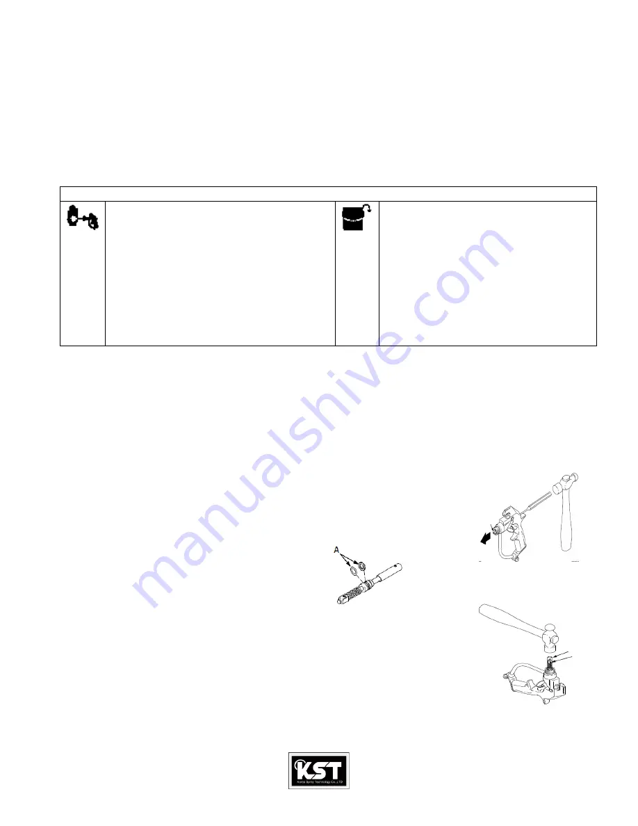
Needle Replacement.
Fig.2
1. Follow the
Pressure Relief Procedure
, page 3.
2. Remove the hose, tip guard, spray tip and gasket. Fig.3
3. Remove the diffuser/seat(6), and gasket(7). Remove the screw(12), pivot pin(13), and trigger(14), page 5.
4. Insert a punch into the rear of the gun and tap it to push the needle(8), out the front of the gun. See Fig 2
5. Clean the internal passages of the gun.
6. Grease the rings(A) of the new needle(8). See Fig.3
7. Side the rear of the needle(8), into the front of the gun. Side the(B), provided with the repair kit, into the gun,
Around the needle. Lightly tap the tool with a hammer or lightly press the tool against a flat surface to seat the
Needle. See Fig. 4. Remove the tool.
-
CAUTION
: Tapping or pressing the tool too hard may jam the tool and damage the needle.
8. Grease the end of the needle.
9. Grease the diffuser/seat threads. Place the new gasket(7), on the diffuser/seat(6), and screw the assembly into the
Fluid housing(11), Torque to 20-25ft-lb(27-34N.m). See Fig. 4
10. Install the trigger(14), pivot pin(13), and screw(12). page 5.
Fig.4
8
B
8


