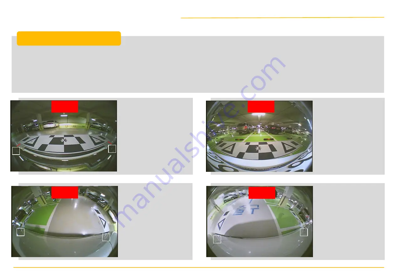
KSS-ImageNEXT SVM Скачать руководство пользователя страница 13

Page 13

1

2

3

4

5

6

Front

Rear

Left

Right

1. The calibration pattern must be installed on FLAT surface.

2. The calibration pattern should align with the front bumper through the monitor.

3. If the calibration pattern is not installed correctly, the result may not be reliable despite the correct camera installation. 

4. If the floor has grid lines, it would certainly help the calibration process. 

5. The distance of the pattern from the driver side must be identical with it is from the passenger side. 

This image on the 

left is an ideal view 

image of the front 

pattern installation.

The distance from 

both left (#1) and 

right (#2) side of the 

front bumper should 

look identical as 

shown in the image. 

The pattern for the rear 

view should be installed 

aligning with the center 

of vehicle. It is rare to be 

able to install the rear 

camera right in the center 

of bumper; Therefore, 

using a tape measure is 

recommended for 

accuracy when installing 

the pattern. 

For the left and the 

right side, the distance 

to the front & rear 

triangle from the 

vehicle should be 

identical. If not, the 

patterns need to be 

re-installed. 

In result of perfect 

calibration, #4 on the 

left and #5 on the right 

should be the same 

distance from the 

vehicle as well as #3 on 

the left and #6 on the 

right. Use the key 

button/mode button to 

switch and confirm each 

view.  

REMARKS

Calibration Pattern Installation

Содержание SVM

Страница 1: ...SVM User Manual Installation Calibration April 2018...

Страница 2: ...Contents 1 SVM Installation 3 Capturing Calibration Views SB NS HDNS 4 Calibration Tool Instruction 5 How to Update Calibration 2 Calibration Pattern Installation...

Страница 3: ...Contents SVM Surround View Monitoring Installation...

Страница 4: ...FRONT Front Camera Installation Front Garnish Type A SVM Installation Page 4...

Страница 5: ...FRONT Front Camera Installation Front Garnish Type B Page 5 SVM Installation...

Страница 6: ...FRONT Front Camera Installation Front Garnish Type C Page 6 SVM Installation...

Страница 7: ...SIDE Side Garnish Use 31 hole saw 1 2 Page 7 Up Down Car Side SVM Installation...

Страница 8: ...from the center as it is difficult to install the camera right in the center due to various reasons In this case other types of rear cameras require adjusting the camera in order to point the center...

Страница 9: ...downward angle and the rear bumper should be shown in the view No more than 40 of the vehicle should be shown in the view Front Side View The camera should be installed on the front side with 25 30 do...

Страница 10: ...the front center of the car If not calibration may not be possible 3 Cameras have designated up down left right sides and they cannot be modified with the software Refer the pictures below for the co...

Страница 11: ...Contents Calibration Pattern Installation...

Страница 12: ...ng If the installing site does not have sufficient space the rectangles on each side can be folded and does not have to be shown 4 All four 4 views Front left right rear should display both triangles...

Страница 13: ...he distance from both left 1 and right 2 side of the front bumper should look identical as shown in the image The pattern for the rear view should be installed aligning with the center of vehicle It i...

Страница 14: ...Contents Capturing Calibration Views SB NS OmniDrive...

Страница 15: ...equired for capturing calibration views and installing updates Insert the SD card which has the captured view files saved to the calibration kit and connect the kit to the ECU for the updates as shown...

Страница 16: ...Key Button Mode Button for 2sec Hold Key Button Mode Button for 2sec Hold Key Button Mode Button for 3sec Hold Key Button Mode Button for 3sec Location of Updates Files Top Level of the SD Card Config...

Страница 17: ...please contact KSS ImageNext Initial Updating Screen Front Camera View When the captured image files ovNS cmd capture cmd downloaded via OVC website or E mail ovNS cmd capture cmd is inserted the fro...

Страница 18: ...in order of Front Rear Left Right After checking the views completely hold the mode button for 3 seconds to save the images on the SD Card ovNS image Capturing View Capturing Completed Save Camera Ima...

Страница 19: ...Contents How to Download Calibration Program...

Страница 20: ...d Calibration Program Log in to www omnivue co kr You need to be approved upon the registration 1 Click OVC CENTER 360 OmniVue Calibration Program and Manual 2 3 4 Unzip the attachments Download all t...

Страница 21: ...Page 21 Click 360OmniVue_Calibration_Program folder and execute setup exe file 5 Once the installation is completed the following icon will appear on your Desktop Download Calibration Program...

Страница 22: ...VIEW image and NS FULL TOP VIEW image file for calibration 3 Parking Guidance Lines OmniVue Parking Guidance Lines image file There is also a file to delete the lines if not required 4 Captured File F...

Страница 23: ...Contents Calibration Tool Instructions...

Страница 24: ...the prior written consent of KSS ImageNext is strictly prohibited Please follow the instruction carefully If the calibration pattern and the cameras are installed impeccably the calibration should be...

Страница 25: ...o load the necessary calibration file based on the correct model NS SB Drive vehicle type Passenger RV Heavy To load the captured view images from all four 4 cameras for calibration To edit all the vi...

Страница 26: ...nfig Load button on the menu 2 When a new window opens click browse button on the right Image 1 3 Go to Desktop 360OmniVUE_Calibration_AssociatedFiles Image 2 4 Select the correct model folder and ope...

Страница 27: ...nd load the captured view images 3 1 Insert the SD card to your PC 2 Click Image Load button 3 When Open File window opens select the SD card drive then click Load button 4 The captured view images wi...

Страница 28: ...te position of all the apexes on every view front rear left and right If inaccurate positions are marked it could be possible for the view or the line to look distorted Each apex has an assigned numbe...

Страница 29: ...marking the apexes To mark the apex click the left button on the mouse whereas click the right button on the mouse to tune The arrows on the keyboard can be used to tune in detail 4 Front Rear Camera...

Страница 30: ...oomed in view is needed for accuracy To return to the previous view double click again 4 For instance when FRONT view is double clicked a zoomed in view will appear in order to mark the accurate posit...

Страница 31: ...Page 31 After marking the apexes select button for Preview window You will be able to set up each view on the Preview window 5 Calibration Tool...

Страница 32: ...will be easier to have both default screen and Preview window on when editing on the Preview window refer to the pictures below 5 When TOP VIEW seems distorted move the marks on the apexes a bit in al...

Страница 33: ...icking Parking Line Assistance 10 Select VIEW_REAR_FULL view adjust the view for the best look 11 Select VIEW_LEFT view adjust the view for the best look This view should be a mirrored view of VIEW_RI...

Страница 34: ...34 Adjust the size of mask area in order to cover the vehicle on the screen by editing the values on Overall width and Overall length fields Preview Screen Set Up 1 Adjust the Mask Area Calibration T...

Страница 35: ...tes below Preview Screen Set Up 1 Adjust the mask area complete Move the screen upward without moving the mask area Move the screen to the right without moving the mask area Move the screen to the lef...

Страница 36: ...Page 36 This step is to load the appropriate vehicle image which is provided with the program to cover the mask area Preview Screen Set Up 2 Upload the Vehicle Image Calibration Tool...

Страница 37: ...in the mask Apply button must be clicked when finished If another modification is needed click Load Car Image and repeat the steps Preview Screen Set Up 2 Upload the Vehicle Image complete Make sure t...

Страница 38: ...Page 38 Similar to the previous view adjust the size of vehicle image with your mouse to fit in the mask Preview Screen Set Up 3 nsFTop View Vertical Image Calibration Tool...

Страница 39: ...Page 39 Apply button must be clicked when finished If another modification is needed click Load Car Image and repeat the steps Preview Screen Set Up 3 nsFTop View Vertical Image Calibration Tool...

Страница 40: ...Page 40 Similar to the previous view adjust the size of vehicle image with your mouse to fit in the mask Preview Screen Set Up 4 nsRTop View Vertical Image Calibration Tool...

Страница 41: ...Page 41 Apply button must be clicked when finished If another modification is needed click Load Car Image and repeat the steps Preview Screen Set Up 4 nsRTop View Vertical Image Calibration Tool...

Страница 42: ...Page 42 Similar to the previous view adjust the size of vehicle image with your mouse to fit in the mask Preview Screen Set Up 5 nsLSTop View Vertical Image Calibration Tool...

Страница 43: ...Page 43 Apply button must be clicked when finished If another modification is needed click Load Car Image and repeat the steps Preview Screen Set Up 5 nsLSTop View Vertical Image Calibration Tool...

Страница 44: ...k Set up the best view utilizing left right up down arrows rotation buttons and zoom in out buttons no need to save Preview Screen Set Up 6 VIEW_FRONT View Adjustment Rotate the image to the left or r...

Страница 45: ...ed in order for more accurate calibration Guides can be selected on each view by clicking the right button on your mouse check Show Guides Preview Screen Set Up 6 VIEW_FRONT View Adjustment Displaying...

Страница 46: ...Set up the best view utilizing left right up down arrows rotation buttons and zoom in out buttons no need to save Preview Screen Set Up 7 VIEW_FRONT_FULL View Adjustment Rotate the image to the left o...

Страница 47: ...Set up the best view utilizing left right up down arrows rotation buttons and zoom in out buttons no need to save Preview Screen Set Up 8 VIEW_REAR View Adjustment Rotate the image to the left or righ...

Страница 48: ...is selected Parking Line Assistance button on the left bottom corner becomes active Then click Parking Line Assistance button and load _ bmp file Preview Screen Set Up 9 Parking Line Assistance in VIE...

Страница 49: ...t right off of the bumper If the parking guidance lines are too far away from the bumper you may decrease the value in Overall length If too close from the bumper increase the value Preview Screen Set...

Страница 50: ...up the best view utilizing left right up down arrows rotation buttons and zoom in out buttons no need to save Preview Screen Set Up 10 VIEW_REAR_FULL View Adjustment Rotate the image to the left or r...

Страница 51: ...L view is selected Parking Line Assistance button on the left bottom corner becomes active Then click Parking Line Assistance button and load _ bmp file Preview Screen Set Up 10 VIEW_REAR_FULL View Ad...

Страница 52: ...rt right off of the bumper If the parking lines are too far away from the bumper you may decrease the value in Overall length If too close from the bumper increase the value Preview Screen Set Up 11 P...

Страница 53: ...own arrows rotation buttons and zoom in out buttons no need to save Preview Screen Set Up 12 VIEW_LEFT View Adjustment 1 Rotate the image to the left or right Adjust the size of screen Tip For the opt...

Страница 54: ...ng left right up down arrows rotation buttons and zoom in out buttons no need to save Preview Screen Set Up 12 VIEW_LEFT View Adjustment 2 Tip For the optimal view minimize the size of vehicle shown i...

Страница 55: ...own arrows rotation buttons and zoom in out buttons no need to save Preview Screen Set Up 13 VIEW_RIGHT View Adjustment 1 Rotate the image to the left or right Adjust the size of screen Tip For the op...

Страница 56: ...ng left right up down arrows rotation buttons and zoom in out buttons no need to save Preview Screen Set Up 13 VIEW_RIGHT View Adjustment 2 Tip For the optimal view minimize the size of vehicle shown...

Страница 57: ...Page 57 Close Preview screen and select Save LUT button from the menu When Save As window pops up select your SD card location Removable Disk and click OK 6 Calibration Tool...

Страница 58: ...Page 58 Depending on the PC No Response warning might appear but eventually everything will be saved in a few minutes Once finished Output file save successfully message will appear 6 Calibration Tool...

Страница 59: ...Contents How to Update Calibration...

Страница 60: ...SD card with the complete calibration file to the calibration kit connected to the ECU then connect to the power 2 Please insert SD card Once the SD card is in place the updates will start automatical...

Страница 61: ...ment in a residential area is likely to cause harmful interference in which case the user will be required to correct the interference at his own expense The users manual or instruction manual for an...

Страница 62: ...THANK YOU...

Отзывы: