KSB M 1 Скачать руководство пользователя страница 6

2 Safety

6 of 20

M 1 (K) Alarm Contactor

2 Safety

!

DANGER

All the information in this section refers to hazardous situations.

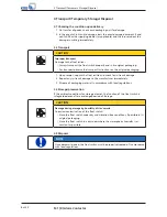
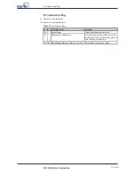
2.1 Key to safety symbols/markings

Table 3: 

Definition of safety symbols/markings

Symbol

Description

!

DANGER

DANGER

This signal word indicates a high-risk hazard which, if not avoided,
will result in death or serious injury.

!

WARNING

WARNING

This signal word indicates a medium-risk hazard which, if not
avoided, could result in death or serious injury.

CAUTION

CAUTION

This signal word indicates a hazard which, if not avoided, could
result in damage to the machine and its functions.

General hazard

In conjunction with one of the signal words this symbol indicates a
hazard which will or could result in death or serious injury.

Electrical hazard

In conjunction with one of the signal words this symbol indicates a
hazard involving electrical voltage and identifies information about
protection against electrical voltage.

Machine damage


In conjunction with the signal word CAUTION this symbol indicates
a hazard for the machine and its functions.

2.2 General

This manual contains general installation, operating, and maintenance instructions
that must be observed to ensure that the float switch is operated safely as well as to
prevent injury and damage to property.

The safety information in all sections of this manual must be complied with.

The manual must be read and fully understood by the specialist personnel/operators
responsible prior to installation and commissioning.

The contents of this manual must be available to the specialist personnel on site at all
times. Instructions attached directly to the float switch must always be complied with
and kept in a perfectly legible condition. This applies to, for example:

Markings for connections

Name plate

The operator is responsible for ensuring compliance with all local regulations not
taken into account in this manual.

2.3 Intended use

The values specified in the technical documentation for the mains voltage, mains
frequency, ambient temperature, and motor current must not be exceeded. The float
switch must only be operated in accordance with the instructions provided in the
operating manual and other applicable documents .

2.4 Personnel qualification and training

All personnel involved must be fully qualified to transport, install, operate, maintain
and inspect the machinery this manual refers to. The responsibilities, competence and
supervision of all personnel involved in installation, operation, maintenance and
inspection must be clearly defined by the operator.

Содержание M 1

Страница 1: ...Magnetic Float Switch M 1 K Alarm Contactor M 1 for AS 0 2 4 5 AS W4 AS W8 M 1 K for AS 1 M and washing machine interrupter GEWAS 191 AN GL Installation Operating Manual...

Страница 2: ...contents provided herein must neither be distributed copied reproduced edited or processed for any other purpose nor otherwise transmitted published or made available to a third party without the man...

Страница 3: ...upon delivery 8 3 2 Transport 8 3 3 Storage preservation 8 3 4 Disposal 8 4 Description 9 4 1 General description 9 4 2 Designation 9 4 3 Name plate 9 4 4 Design details 9 4 5 Technical data 10 5 Ins...

Страница 4: ...l in the collecting tank of a waste water lifting unit is too high Features the following supplementary functions alarm buzzer indicator lamps for operational availability and high water luminous swit...

Страница 5: ...group This operating manual is aimed at the target group of trained and qualified specialist technical personnel 1 3 Other applicable documents Table 1 Overview of other applicable documents Document...

Страница 6: ...served to ensure that the float switch is operated safely as well as to prevent injury and damage to property The safety information in all sections of this manual must be complied with The manual mus...

Страница 7: ...damages Non compliance can for example have the following consequences Hazards to persons due to electrical thermal mechanical and chemical effects and explosions Failure of important product function...

Страница 8: ...al packaging 1 Upon receipt unpack the float switch and check for in transit damage 2 Report any in transit damage to the manufacturer immediately 3 Dispose of packaging material in accordance with lo...

Страница 9: ...mple M 1 K alarm contactor Table 4 Key to the designation Code Description Alarm contactor Type series M Magnetic float switch 1 Code number K With contact plug for washing machine interrupter only 4...

Страница 10: ...V Start up current Max 0 5 A Switching capacity 10 VA Temperature range Up to 60 C Enclosure IP 67 Immersion depth 2 m Immersion time 7 days Initial function Circuit closed in upper float position NO...

Страница 11: ...C 60364 DIN VDE 0100 DANGER Power supply not disconnected Danger to life Pull the mains plug or disconnect all electrical connections and secure against unintentional start up DANGER Flooding of contr...

Страница 12: ...r Box 1U 1B single pump units 1 Fasten clamp 733 to bracket 732 02 using cheese head screw 900 disc 550 and hexagon nut 920 2 Fasten float switch 81 45 to the bracket width across flats 17 see alarm c...

Страница 13: ...ual pump units 1 Fasten float switch 81 45 to bracket 732 02 width across flats 17 see alarm contactor M 1 K installation drawing below 2 Fasten the pre assembled bracket with float switch to cross be...

Страница 14: ...k Always have the electrical connections installed by a trained and qualified electrician Observe regulations IEC 60364 DIN VDE 0100 M 1 alarm contactor Please refer to the wiring diagram Section 9 1...

Страница 15: ...ual for alarm switchgear AS 0 AS 1 M AS 2 AS 4 AS 5 and the washing machine interrupter is complied with M 1 alarm contactor and alarm switchgear AS 0 AS 2 AS 4 AS 5 AS W4 or AS W8 have been connected...

Страница 16: ...ontactor 7 Maintenance Operating reliability will be improved if proper functioning of the contactor is checked and verified at regular intervals The contactor should be checked for deposits every 3 m...

Страница 17: ...arm is not deactivated Table 6 Trouble shooting A B Possible cause Remedy No voltage Check electrical connections Reed contact defective Carry out continuity check on alarm contactor with an ohmmeter...

Страница 18: ...0 AS 2 AS 4 AS W4 AS W8 3 5 AS 0 AS 2 AS 4 AS W4 AS W8 M 1 a b Fig 8 Wiring diagram for M 1 alarm contactor to alarm switchgear AS 0 AS 2 AS 4 AS W4 AS W8 a White WH b Brown BN M 1 alarm contactor to...

Страница 19: ...Index 19 of 20 M 1 K Alarm Contactor Index C Commissioning start up 15 F Faults Trouble shooting 17 O Other applicable documents 5 S Safety awareness 7 T Transport 8...

Страница 20: ...KSB SE Co KGaA Johann Klein Stra e 9 67227 Frankenthal Germany Tel 49 6233 86 0 www ksb com 2315 813 05 EN...

Отзывы: