Submersible motor pumps (100 mm)
5
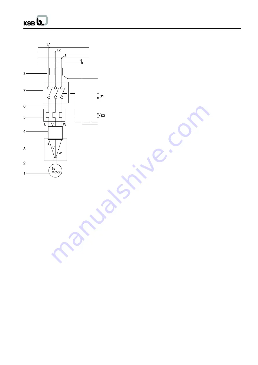
2.4.2 For three-phase motor
1. Submersible motor
2. Motor cable
3. Cable designation
4. Connected cable
5. Overload relay (thermal type)
6. Leads
7. Electro-magnetic switches
8. Fuses
L1, L2, L3 = Line supply
U, V, W
= Leads
N
= Neutral
S1, S2
= Push buttons
* Overload relay must be thermal type.
3
Commissioning and start up
3.1
Verification of rated current
Please refer to the motor nameplate for the values of rated current
required for relay setting.
3.2
Switching ON of mains
The pumping set should be switched on only if it is fully immersed
in the water.
3.3
Checking the direction of rotation
For three-phase motors
1. Let the pumping set run for a short time against a closed
discharge valve, in both the directions of rotation and check
the flow. Reversing of two points of connection, reverses
the direction of rotation. The higher flow rate gives the
direction of rotation. OR
2. Using pressure gauge, check the discharge pressure in both
the direction of rotations. The higher value corresponds to
the correct direction of rotation. OR
3. By visual inspection see the flow rate in both cases. If water
comes out up to the short length through the raiser pipe, flow
rate is lower while if it comes farther, results in higher flow
rate. The higher flow indicates the correct direction of rotation.
For Single-phase motors
In case of single-phase AC motors the direction of rotation of the
motor itself corresponds to the correct direction of rotation of the
pump, irrespective of mode of connection to the power supply.
3.4
Discharge valve position during initial start-
up
During initial start-up the pump should run with the discharge
valve slightly open (approx. 1/3 of full opening). The water is
examined for sand content (The permissible sand contents for
warranty is 50 mg / liter) at this stage it is important that pump is
run continuously without stooping (if pump is stop, sand will settle
inside the pump and pump is block resulting in damage) till the
sand content in the water falls to an unnoticeable level
OR Flush
the bore well completely before new pump installation.
3.5
Operation against a closed discharge valve
Pumps should not be allowed to run against a closed discharge
valve for longer than 5 minutes. This would cause the water in
the pump to warm up quickly and the heat would be transferred
to the motor, which causes a risk to the motor.
3.6
Operation against a throttled discharge valve
If the pump set is to be operated against a throttled discharge
valve for a prolonged period of time, the minimum rate of flow
should be at least 10% of flow at the best efficiency point * (BEP)
of the characteristic curve, this must be observed in order to
reduce noisy operation and the overheating of the pump set.
* For best efficiency point (BEP) of the characteristic curve
consult with KSB dealer.
Actual start-up
• Check the power supply condition as per the name plate.
• Do proper earthling.
• Fix the pressure gauge before discharge valve.
• Set the relay as per current value given on name plate and
start the pump.
• Set the duty parameters as per value given on name plate by
control valve.
• Pump should run always on duty point specified on name plate
3.7
Operating limits of pump
Operational safety requirements stipulate that pump may only
be operated continuously within the flow rate and pump head
limits which are specified on nameplate. Otherwise ±10% of best
efficiency flow rate should be the pump operation range, provided
that motor is not overloaded. (For ensuring this the motor current
should not exceed as specified on name plate).
3.8
Switching frequency
In order to prevent the motor from heating up excessively due to
many switching cycles, a maximum of 15 starts per hour are
permitted with a minimum of 3 minutes interval as a shut down
period between two successive starts.


