background image

Before Use: Preparing the Robot Trolley 


Checking the status 

1.


Unpack the Robot Trolley and check that the Robot Trolley is clean and not broken 

2.


Make sure the Robot Trolley battery is charged according to instructions 


Mounting the suspension fitting 

 standard bracket

2


REGIONAL VARIANTS 

Some countries and makes of caravan may require a special bracket version. Please inquire with your dealer. 


If there is a plastic cover over the side member system on the caravan, it can be helpful to remove it while mounting the 

suspension fitting. 


1.


When mounting the suspension fitting from the Robot Trolley onto the caravan, start by gliding the two mounting 

tubes, A1 and A2, together, and then placing them up inside the side members. 

2.


Next, loosely screw on the mounting bracket to the inner mounting tube, and screw the female piece to the 

mounting bracket. If there are larger distances between side members, place the extension tube inside the inner 

mounting tube. 


The illustration below shows the assembled suspension fitting mounted on the side members: 


3.


Slide the entire suspension fitting as far back on the side members as possible to put maximum weight on the 

Robot Trolley. Do not push the suspension fitting so far back that mounting and removing the Robot Trolley 

becomes difficult. 


The following illustration shows the optimal placement of the suspension fitting on the caravan: 


4.


Push the Outer and Inner Mounting Tube as far from each other as possible, towards the sides of the side 

members. Tighten the left and right brackets so that the bent undersides of these are positioned precisely against 

the outer side of the side members. Make sure that the bolts are tightened to the maximum extent. 

(If the caravan’s bearers are extremely narrow, and the 

mounting tubes cannot be pressed far enough together 

upon mounting, you can use a hacksaw to shorten mounting tube A2. There must be minimum 10-15 cm inner 

overlap of the Outer and Inner mounting tubes.) 

5.


Once the suspension fitting is adjusted and fastened to the side members, tighten the clamp bolt into the side of 

the inner mounting tube. 

2


Suspension fitting brackets are NOT included in default configuration for RT2500RS model


A1: Outer mounting tube 

Female for mounting bracket


Mounting bracket for 

inner mounting tube 

Inner extension tube 

A2: Inner mounting tube 

5

Содержание 2500RS

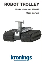
Страница 1: ...ROBOT TROLLEY Model 4500 and 2500RS User Manual ...

Страница 2: ... after use until the LED light turns green Recharge Periodically If the Robot Trolley goes unused for more than two months it is highly recommended to inspect and charge the battery until the LED on the charger changes from red to green in order to maintain maximum battery life and performance Do not store the Robot Trolley in direct sunlight or at high temperatures High temperatures may drain the...

Страница 3: ...rox 12 5 m min Motor 4 x DC motors 4 x DC motors Safety function 3 min Auto shut off 3 min Auto shut off Hauling capacity Trailers up to 4 500 kg Trailers up to 2 500 kg Caterpillar tracks 2 with rubber profiles 2 with rubber profiles Weight Approx 35 kg Approx 35 kg Contents of carton When unpacking the Robot Trolley please check that all parts are in the carton If any of the items are missing Co...

Страница 4: ...ey RT4500 and RT2500RS have been manufactured in conformity with the provisions of the following EC directives 98 37 EC The Machinery Directive 99 5 EC The R TTE Directive 2004 108 EC The EMC Directive 2002 95 EC The RoHS Directive 2002 96 EC The WEEE Directive 2006 42 EC The EU machine directive and that all standards mentioned overleaf have been applied The last two digits of the year of the CE ...

Страница 5: ...revention of unexpected start up EN 12100 1 2005 Safety of Machinery Basic concepts and general principles for design Part 1 Basic terminology methodology EN 12100 2 2005 Safety of Machinery Basic concepts and general principles for design Part 2 Technical principles EN 13850 2006 Safety of Machinery Emergency stop Principles for design EN 13857 2008 Safety distances to prevent hazard zones being ...

Страница 6: ...tire suspension fitting as far back on the side members as possible to put maximum weight on the Robot Trolley Do not push the suspension fitting so far back that mounting and removing the Robot Trolley becomes difficult The following illustration shows the optimal placement of the suspension fitting on the caravan 4 Push the Outer and Inner Mounting Tube as far from each other as possible towards...

Страница 7: ...odel RT2500RS In order for Robot Trolley to function optimally the ball weight must be at least 75 85 kg This ball weight creates about 120 150 kg of pressure on the Robot Trolley Too little weight on the Robot Trolley may result in poor gripping and poor towing results Greatest pressure is achieved by mounting the Robot Trolley as far back on the side members as possible 3 Level surfaces To ensur...

Страница 8: ...n strong sunlight The maneuvering buttons on the remote control RT4500 model Forward Turn right Backward Turn left The battery indicator shows the Robot Trolley s remaining battery status If the capacity is too low the CT may not respond correctly If the indicator itself weakens the remote control battery needs to be replaced otherwise the CT may not respond correctly Maneuvering the Robot Trolley...

Страница 9: ...give it a gentle cleaning using a small amount of clean water and a brush or cloth Do not use soap or cleansing agents or a high pressure cleaner Storage Put the Robot Trolley in the transport box bag delivered from the factory If the storage box bag should become damaged discard it A new plastic storage box bag may be obtained from your Robot Trolley distributor Store the Robot Trolley in dry fro...

Отзывы: