11
EN Application sheet
EN Application sheet
KITCHEN HOODS
separately). The non-return valve prevents the
air penetration from the vent flue back to the
kitchen.
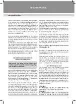
10. Connect the free end of the exhaust pipe to
the air inlet in the kitchen. Avoid unnecessary
twisting of the exhaust pipe. The shorter and
the straighter the exhaust pipe is, the higher is
the performance of the cooker hood, and the
less is its vibration.
11. If you use the cooker hood in recirculation
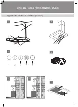
mode, install the decorative chimneys (see Fig.
1, no. 5, 6).
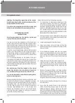
Mark points for fixing the bracket of the deco-
rative chimneys (see Fig. 10, points E, F).
12. Drill two holes 6 mm in diameter 5 cm lower
than the kitchen ceiling level.
13. Insert the two wall plugs Ø 6 into the holes and
fix the bracket for the decorative chimneys on
the points E, F.
14. Before mounting the decorative chimneys,
connect the cooker hood to the power source.
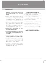
15. Put the internal decorative chimney inside the
external chimney. Mount the external chimney
onto the cooker hood body (if there are fixing
points on the chimney and the cooker hood
body, use screws to fix the chimney).
16. Lift the internal decorative chimney up to the
level where it reaches the fixing bracket and
join them together (Pic. 10.2).
CONNECTION TO POWER SUPPLY
The kitchen hood is connected to the power net-
work with the voltage of 220-240V, 50 Hz.
The kitchen hood should be connected to a wall
outlet with earthing to avoid electrocution.
It is absolutely prohibited to cut off the plug
during kitchen hood installation.
The damaged electrical cord should be re-
placed by a qualified service specialist.
For additional protection of the kitchen hood from
voltage drops in the network, connect it though an
additional automatic switch 6A.
The kitchen hood is installed.
Switch it on and use it as you please.


