


TC 1, TC 2, TC 3 · Edition 07.22
EN-4
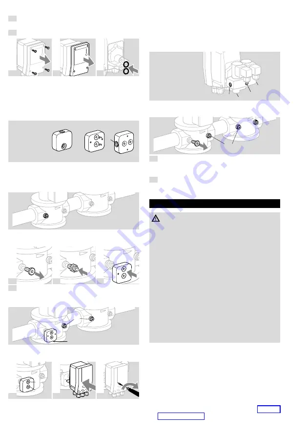
3.3 Mounting tC 2
1
Disconnect the system from the electrical power
supply.
2
Close the gas supply.
3
4
5
➔
The O-rings must be inserted in the connectors
of the TC.
➔
Connect the TC to the inlet pressure connection p
u
and the interspace pressure connection p
z
of the
inlet valve.
➔
Use the adapter plate supplied for installation.
TC 2..R: Rp ¼
TC 2..N: ¼ NPT
p
u
p
z
p
z
➔
We recommend using Ermeto screw couplings to
attach the adapter plate to the gas solenoid valve.
It may be necessary to compensate the distance
to the valve housing.
p
u
p
u
➔
Only use approved sealing material to seal the pipe
connections.
6
7
8
9
Connect the interspace pressure connection p
z
on
the adapter plate to the space between the valves
using a 12 x 1.5 or 8 x 1 pipe.
p
u
p
z
p
z
➔
Ensure that connections p
u
and p
z
on the TC and
adapter plate are not reversed.
10
p
u
p
z
11
12
250 Ncm
3.4 Mounting tC 3
➔
Connect the TC to the inlet pressure connection p
u
,
the interspace pressure connection p
z
and the
outlet pressure connection p
d
of the inlet valve.
Ensure that connections p
u
, p
z
and p
d
on the TC
are not reversed.
p
z
p
z
p
d
p
u
TC 3..R: Rp ¼
TC 3..N: ¼ NPT
➔
Use a 12 x 1.5 or 8 x 1 pipe for the pipe con-
nections.
p
u
p
d
p
z
1
Mount TC 3.
➔
Only use approved sealing material to seal the pipe
connections.
2
Seal the unused connection p
z
on the TC using
the sealing plug supplied.
4 WIRInG
WARnInG
Risk of injury!
Please observe the following to ensure that no
damage occurs:
– Electric shocks can be fatal! Before working on
possible live components, ensure the unit is
disconnected from the power supply.
– Incorrect wiring may result in unsafe states and
the destruction of the tightness control, the
automatic burner control unit or the valves.
– Do not reverse L1 (+) and N (–).
– Cable cross-sections must be designed for the
current rating of the selected external fuse.
– The valve outputs on the automatic burner
control unit connected to the TC must be
safeguarded by an external slow-acting fuse of
max. 5 A (e.g. in the automatic burner control
unit).
➔
Wiring to EN 60204-1.
➔
Use connection terminals with a cable cross-sec-
tion of max. 2.5 mm
2
.
➔
Conductors which have not been connected (spare
conductors) must be insulated at their ends.
➔
Do not set the remote reset so that it operates
(automatically) in cycles.
➔
The data on the type label must comply with the
mains voltage.
➔
Length of the connection cable, see page 10
(11 Technical data).


