


GB-2
D
GB
F
NL
I
E
Checking the usage
UV sensor for intermittent operation for flame
control on gas burners in conjunction with Elster
Kromschröder automatic burner control units (IFS,
IFD, PFS, PFD), flame detectors (IFW, PFF) or burner
control units (BCU, PFU).
This function is only guaranteed when used within the
specified limits – see page 5 (Technical data). Any
other use is considered as non-compliant.
Type code
Code
Description
UVS
UV sensor
5
Series 5
G1
Electrical connection:
M20 cable gland
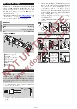
Part designations
4
3
2
1
2
3
4
6
7
8
5
1
M20 cable gland
2
Housing
Spring force terminals
4
Sensor head
5
Positioning aid
6
Sticker
7
UV tube
8
Bracket
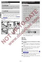
Installation
CAUTION
Use UV sensor only in conjunction with Elster
Kromschröder automatic burner control units,
flame detectors or burner control units in order to
avoid damage.
▷
It is preferable to install the unit inclined from
above or in the horizontal.
< 400mm
(16”)
▷
Distance between UVS and flame: max. 400 mm
(16").
▷
The UV sensor may only be exposed to the UV
light of its own flame. It should be protected
from other sources of ultraviolet light, e.g. neigh-
bouring flames (this must be observed when
monitoring pilot and main burners in particular),
ignition sparks, arcs from welding devices or
lamps emitting ultraviolet light.
▷
Avoid exposing the UV sensor viewing openings
to direct sunlight.
▷
Protect the viewing openings against dirt and
moisture.
4,5
N
24
18
18
2
1
4
5
3
Direct at the flame from the front or side.
Positioning aid
to allow sim-
ple alignment
when replac-
ing sensors/
tubes.


