KROHNE OPTIWAVE 400 Series Скачать руководство пользователя страница 22

3

 ELECTRICAL CONNECTIONS 

22 

OPTIWAVE X400

www.krohne.com

06/2021 - 4006413503 - AD NEPSI OPTIWAVE x400 R03 en

3.6  Ex d ia / Ex iaD tD equipment

3.6.1  General notes

Ex d ia- and Ex iaD tD-approved equipment have two separate compartments. The electronics in 
the electronics block compartment are Ex ia-approved and the terminal compartment is Ex d / 
Ex tD-approved.

3.6.2  How to connect the electrical cables

Cable glands are supplied on customer demand. If you supply the cable glands, this part must 
have a degree of ingress protection IP

6X (IEC 60529). We recommend that you use a part that 

has a degree of ingress protection IP

68. Make sure that the cable gland is sealed.

Terminal compartment

If you connect electrical wires to the terminals in the flameproof terminal compartment, use 
approved flameproof cable glands (M20×1.5 or 

½

NPT). The cable glands must have a 

certificate that agrees with GB 3836.1 and GB 3836.2. Obey the instructions given on the 
certificate. Make sure that the tightening capacity of the cable gland is applicable to the 
diameter of the electrical wire.

If you use conduits to connect electrical wires to the terminals in the flameproof terminal 
compartment, obey the instructions that follow. Make sure that the conduits are correctly 
attached and the flameproof compartment is sealed. The conduits must have a certificate 
that agrees with GB 3836.1 and GB 3836.2. Use conduit stopping boxes that agree with 
precautions given in the certificate and data in standards related to the installation of the 
conduit.

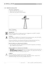
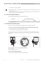
Figure 3-4: Compartments in Ex d ia- and Ex iaD tD-approved equipment

1  

Electronics block (Ex ia) compartment

2  

Terminal (Ex d / Ex tD) compartment

DANGER!

If you must open the electronics block compartment to remove the electronics blocks for 
servicing, de-energize the device. It is not necessary to disconnect the wires from the Ex d / 
Ex tD terminals.

If you must remove the terminal block for servicing, do not open the terminal compartment in a 
potentially explosive atmosphere.

WARNING!

Use only Ex d-approved cable glands and adaptors for Ex d applications. Use only Ex tD-
approved cable glands and adaptors for Ex tD applications.

Содержание OPTIWAVE 400 Series

Страница 1: ...applications Supplementary Instructions for NEPSI applications Supplementary Instructions for NEPSI applications OPTIWAVE X400 OPTIWAVE X400 OPTIWAVE X400 OPTIWAVE X400 Supplementary Instructions Sup...

Страница 2: ...eneral notes 18 3 2 Terminal compartment 18 3 2 1 How to open the terminal compartment 18 3 2 2 How to close the terminal compartment 19 3 3 Terminal tightening capacity 20 3 4 Equipotential bonding s...

Страница 3: ...ohne com 06 2021 4006413503 AD NEPSI OPTIWAVE x400 R03 en OPTIWAVE X400 5 8 Returning the device to the manufacturer 28 5 8 1 General information 28 5 8 2 Form for copying to accompany a returned devi...

Страница 4: ...unication or on an optional integrated display screen with wizard driven setup The level transmitter is approved for use in potentially explosive atmospheres when equipped with the appropriate options...

Страница 5: ...IIC T4 T6 Ga Gb OPTIWAVE 7400 All versions Ex ia IIC T3 T6 Ga Gb The Ex ia approved device is suitable for use in potentially explosive atmospheres of all flammable substances in Gas Groups IIA IIB an...

Страница 6: ...and OPTIWAVE 6400 All other versions Ex iaD 20 21 T85 T130 OPTIWAVE 7400 PTFE Drop antenna and all antennas with EPDM gasket Ex iaD 20 21 T85 T150 OPTIWAVE 7400 All other versions Ex iaD 20 21 T85 T20...

Страница 7: ...OPTIWAVE 7400 All versions Ex d ia IIC T3 T6 Ga Gb The Ex d ia approved device is suitable for use in potentially explosive atmospheres of all flammable substances in Gas Groups IIA IIB and IIC It is...

Страница 8: ...0 All other versions Ex iaD 20 21 tD A21 IP6X T85 C T130 C OPTIWAVE 7400 PTFE Drop antenna and all antennas with EPDM gasket Ex iaD 20 21 tD A21 IP6X T85 C T150 C OPTIWAVE 7400 All other versions Ex i...

Страница 9: ...iaD approvals Ex ia or Ex iaD approvals Ex ia or Ex iaD approvals Intrinsically safe circuit data Refer to 6 for the input voltage range Ex d ia or Ex iaD tD approvals Ex d ia or Ex iaD tD approvals...

Страница 10: ...ownload the certificate from our internet site DANGER This installation must agree with Chinese Law and NEPSI regulations For more data refer to the related NEPSI explosion protection certificate of c...

Страница 11: ...electrostatic hazard see instructions Figure 2 2 Risk of ESD 1 Sun cover 2 Drop antenna 3 OPTIWAVE 5400 and OPTIWAVE 7400 OPTIWAVE 5400 and OPTIWAVE 7400 OPTIWAVE 5400 and OPTIWAVE 7400 OPTIWAVE 5400...

Страница 12: ...ng fluid temperature must be less than 2 3 of the ignition temperature Dust layers thickness 5 mm 0 2 Dust layers thickness 5 mm 0 2 Dust layers thickness 5 mm 0 2 Dust layers thickness 5 mm 0 2 The d...

Страница 13: ...heating cooling system must not be more than 6 barg 87 psig The process pressure must not be more than 2 barg 29 psig The heating cooling fluid temperature must be less than the ignition temperature...

Страница 14: ...on on the pipe or stilling well and the process connection WARNING An explosive atmosphere is a mixture of air and flammable gases vapour mist or dust in atmospheric conditions If you do not use the d...

Страница 15: ...are for Ex d ia or Ex iaD tD approved devices 2 Max process connection temperature is 100 C if the PP Drop antenna and PP accessories are used Temperature class for EPL Ga Gb EPL Gb or EPL Gc Maximum...

Страница 16: ...tainless steel housing C All classes 1 All surface temperatures 1 40 40 40 37 36 50 1 Min process connection temperature is 15 C if the device has a hygienic antenna with an FKM FPM gasket Min process...

Страница 17: ...ess steel housing C T6 T85 C 60 60 60 50 43 85 T5 T100 C 75 75 67 1 75 65 58 56 1 100 T4 T135 C 67 56 49 1 115 59 43 40 1 135 T3 T150 C 54 33 150 1 Values in parentheses are for Ex d ia or Ex iaD tD a...

Страница 18: ...cable entry size refer to the device nameplate Ex d approved devices Ex d approved devices Ex d approved devices Ex d approved devices Use heat resistant cables and cable glands certified for continu...

Страница 19: ...cover For more data about the procedure refer to the handbook 3 2 2 How to close the terminal compartment Equipment needed Wrench supplied DANGER Ex d applications Ex d applications Ex d applications...

Страница 20: ...e equipotential bonding system for the hazardous location You can use 2 terminals to connect the device to the equipotential bonding system a ground connection in the terminal compartment and an exter...

Страница 21: ...ion procedure in the handbook Put the electrical wires in position and safely attach them to prevent damage The electrical wires must also be a sufficient distance from hot surfaces Make sure that unu...

Страница 22: ...e tightening capacity of the cable gland is applicable to the diameter of the electrical wire If you use conduits to connect electrical wires to the terminals in the flameproof terminal compartment ob...

Страница 23: ...er are isolated from the ground of the hazardous area This data is also applicable to the equipotential bonding conductors PE Make sure that unused electrical wires and shields are safely connected to...

Страница 24: ...o Maximum intrinsically safe values for the electrical circuit on page 21 3 6 4 Maximum voltage for the electrical circuit Um 250 V AC DC For the minimum and maximum supply voltage at the terminals re...

Страница 25: ...lications Ex t applications Ex t applications Ex t applications If you supplied the cable glands and adaptors are these parts Ex t approved Ex i applications Ex i applications Ex i applications Ex i a...

Страница 26: ...vice and disconnect the electrical wires For more data refer to How to open the terminal compartment on page 18 Before you remove the device from the process connection make sure that the tank is not...

Страница 27: ...er with an OPTIWAVE 7400 signal converter If your device was made before June 2009 you must attach an adaptor when you replace the signal converter with an OPTIWAVE 7400 signal converter Use the spare...

Страница 28: ...th these operating instructions it will rarely present any problems WARNING Should you nevertheless need to return a device for inspection or repair please pay strict attention to the following points...

Страница 29: ...ame Telephone number Fax number Email address Manufacturer order number or serial number The device has been operated with the following medium This medium is radioactive water hazardous toxic caustic...

Страница 30: ...6 NOTES 30 OPTIWAVE X400 www krohne com 06 2021 4006413503 AD NEPSI OPTIWAVE x400 R03 en...

Страница 31: ...NOTES 6 31 OPTIWAVE X400 www krohne com 06 2021 4006413503 AD NEPSI OPTIWAVE x400 R03 en...

Страница 32: ...solutions Engineering commissioning calibration maintenance and training services Head Office KROHNE Messtechnik GmbH Ludwig Krohne Str 5 47058 Duisburg Germany Tel 49 203 301 0 Fax 49 203 301 10389 i...

Отзывы: