KROHNE OPTISONIC 7060 Скачать руководство пользователя страница 20

OPTISONIC 7060


Electrical & mechanical installation manual                730962.31.00                                   page 20 of 52 
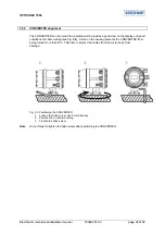
 

3.1.2 

Transport and Storage 


Important 


Only use the hoisting gear and auxiliaries (e.g. lifting straps) suitable for the weight to be 


lifted. Max. load information can be found on the type plate of the hoisting gear. It is strongly 


recommended to use the eye bolts supplied with the device only. 


During OPTISONIC 7060 transport and storage operations, make sure that: 

¾

  The sealing surfaces of the flanges are protected with special caps 

¾

  The measuring device is firmly secures at all times 

¾

  Measures are taken to avoid mechanical damage 

¾

  Humidity and ambient temperature are within specified limits (see Section 

2.2.4

). 


If the device is to be stored outside for more than one day, sealing surfaces of the flanges 


and the interior of the meter body must be protected from corrosion, e.g. with Anticorit spray 


(not required for stainless steel meter bodies). The same measure shall be taken if the 


device is to be stored in dry condition, but for more than a week. 


Note

   Due to natural temperature fluctuation in the course of a day, or if the measuring device is 


transported to a place with different temperature and humidity, moisture will condense on 


any material. Carbon steel surfaces may corrode if left unprotected. 
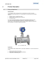
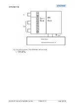
 

3.2 Assembly 


Generally, the installation arrangement is specified during the project planning phase, i.e. 


before installation of the system. Nominal width, material and type of flange should therefore 


be defined in accordance with the design of the existing plant. It is particularly important that 


the internal diameters of the meter body and adjacent pipelines are identical. 


Fixing bolts, nuts and flange seals used must be suited to the operational conditions, and 


comply with legal regulations and relevant standards. 


Note 

  Any deviation from the planned design of the OPTISONIC 7060 and installation arrangement 


shall be agreed with the supplier and documented prior to installing the measuring device. 


Measuring location 


The OPTISONIC 7060 can be installed in customary straight inlet and outlet pipes. The 


adjacent pipes must have the same nominal width as the meter body. The internal 


diameter can be derived from the marked flange standard and the type key information 


(Appendix, Table 8.2). Any welding beads on the flanges of the inlet pipe shall be 


flattened. 


The meter body may be installed in horizontal or vertical position. In case of horizontal 


installation, make sure that the meter body is adjusted so that the measuring planes are 


in horizontal position. This aims to prevent dirt or moisture in the pipeline from entering the 
transducer ports. Vertical installation is only possible if the measuring system is used for dry, 
noncondensing gases. The gas flow must be free from any foreign material, dust and liquids. 


Otherwise, filters and traps shall be used. 


Avoid installations which may adversely affect the gas flow to be mounted directly 


upstream the OPTISONIC 7060. 


Seals at the flange connections between meter body and pipeline must not protrude into 


the pipeline. Otherwise, the flow profile and thus the measuring accuracy may be 


adversely 

affected. 


Temperature measuring devices shall be fitted in the outlet pipe no closer than 1.5x DN, 


or – in case of nominal widths of  


DN 400 – no closer than 300 mm. 


   IMPORTANT


Содержание OPTISONIC 7060

Страница 1: ...KROHNE 10 2006 730962 31 00 Ultrasonic Flowmeters OPTISONIC 7060 Electrical mechanical installation manual...

Страница 2: ...General Notes 19 3 1 1 Delivery 19 3 1 2 Transport and Storage 20 3 2 Assembly 20 3 3 Mechanical Installation 21 3 3 1 Choosing flanges seals and other parts 22 3 3 2 Mounting the OPTISONIC 7060 to th...

Страница 3: ...erminal assignments ATEX 47 8 2 Converter terminal assignments CSA 48 Product Liability and warranty Responsibility for suitability and intented use of these ultrasonic flowmeters rests solely with th...

Страница 4: ...ckage includes the following documents Operating Instructions OPTISONIC 7060 this document Documentation CD Option for trained staff only Service Manual OPTISONIC 7060 Software Manual MEPAFLOW IV Symb...

Страница 5: ...mmunity EN Euro Norm European Standard Ex Potentially explosive atmosphere hazardous area HART Communication interface IEC International Electrotechnical Commission norm normalised standard condition...

Страница 6: ...y possible dangers and to take preventive action in due time Skilled persons shall have precise knowledge of process specific dangers e g due to the effects of hot toxic and pressurised gases gas liqu...

Страница 7: ...compliance with the safety requirements set forth in the European Pressure Equipment Directive 97 23 EC Any relevant information has been taken into account for the particular application as specifie...

Страница 8: ...meter body Concealed cabling As a result this measuring system is extremely robust and provides maximum accuracy even under extremely harsh operating conditions Its compact design also provides prote...

Страница 9: ...imum flowrate Meter size m s ft s m3 h ft3 h m3 h ft3 h m3 h ft3 h DN 50 2 57 187 402 14197 212 7486 74 7 1 249 DN 65 2 5 57 187 680 24014 357 12607 4 11 9 417 DN 80 3 57 187 1000 35315 540 19070 18 6...

Страница 10: ...0227 Measuring rate 20 measurements s Interfaces MODBUS RS 485 ASCII protocol for parameterisation measured value inquiry and diagnosis 9600 8 N 1 Explosion protection Europe II 2G EEx de ib ia IIA or...

Страница 11: ...processing unit Fig 2 3 OPTISONIC 7060 1 Converter 2 Flange 3 Flowmeter body 4 Indication of positive flow direction 5 Transducer holder 2 3 1 Meter Body The meter body consists of a section for moun...

Страница 12: ...ith a PC or standardised process control system Event logging The current volume counter value fault warning and power failure alarms are stored in a see Section battery buffered data memory FRAM alon...

Страница 13: ...ower supply and field connections are located on the back of the CONVERTER in a separate terminal box see Section 3 4 4 The electronics units are mounted in a housing certified to EN 50018 or IEC 6007...

Страница 14: ...uring accurately If the cause for the fault ceases to exist the system returns to Measurement mode automatically Any operating modes are recorded in the logbook together with their respective activati...

Страница 15: ...standard the LCD shows the two major counters one for each direction of flow Changes in the logbook status are indicated by a flashing character at the far right end of the first line of the display...

Страница 16: ...ation time Note When setting the parameters take into account plausible conditions for normal operation in particular temperature stratification 6 dB Warning AGC Deviation The absolute difference betw...

Страница 17: ...e after password input or back from the configuration mode to the measurement mode Parameter modifications that affect the measured values may have been carried out Activated password level Volume cou...

Страница 18: ...nt signal 4 20 mA fault current signal at configuration or malfunction DO 1 51 52 Measured value frequency signal Direction of flow Malfunction Check requested Warning DO 2 41 42 Measured value freque...

Страница 19: ...flanges Any damage must be documented and reported to the manufacturer immediately Also check the consignment for completeness The standard scope of delivery comprises OPTISONIC 7060 measuring system...

Страница 20: ...articularly important that the internal diameters of the meter body and adjacent pipelines are identical Fixing bolts nuts and flange seals used must be suited to the operational conditions and comply...

Страница 21: ...of the flowmeter For bidirectional use inlet and outlet section at both sides of the meter body shall be of identical independent of the configuration used see Fig 3 3 The temperature measuring point...

Страница 22: ...the pipeline using the hoisting gear Only use the hoisting eyes provided to lift and transport the device If you use lifting straps wrap them around the meter body Important The hoisting eyes are des...

Страница 23: ...od conditions for cable routing see Fig 3 4 A stop on the housing prevents the CONVERTER from being turned more than 330 This aims to protect the cables from the meter body from damage Fig 3 4 Positio...

Страница 24: ...ety instructions given in Section 1 when carrying out any installation work Installation work shall only be carried out by trained staff and in accordance with the relevant regulations issued by the o...

Страница 25: ...cable Twisted pair shielded impedance approx 120 Connect shielding at other end to ground terminal Min max cross sectional area 2 x 0 5 mm 2 Maximum cable length 100 m at 0 5 mm 200 m at 1 5 mm Do not...

Страница 26: ...using the insulation resistance tester Important The test voltage applied would seriously damage the electronics unit Reconnect all cables after the loop resistance test Important In non intrinsically...

Страница 27: ...r housing cover Loosen the securing bracket using a 3 mm Allan key Turn the rear housing cover in a counter clockwise direction and take it off A schematic wiring diagram is provided on the inside of...

Страница 28: ...ER 1 Power supply 2x1 5mm2 UYCY or equivalent 2 Digital output current output 4 x 2 x 0 5 mm2 UYCY TP or equivalent 3 Modbus 4 x 2 x 0 5 mm2 UYCY TP or equivalent 4 HSK K cable glands M20 x 1 5 plasti...

Страница 29: ...bit Baud rate to be set through software 4 Digital output D0 1 Passive 51 52 fmax 6 kHz pulse duration 0 05 s 1 s Range Freely selectable number of pulses per volume unit closed 0 V UCEL 2 V 2 mA ICE...

Страница 30: ...tection e where the field connections are intrinsically safe i The user must decide which variant to use taking into account EN 60079 14 A combination of intrinsically safe and non intrinsically safe...

Страница 31: ...are black If connections are wired with intrinsically safe circuits it is recommended to replace these with the light blue cable connections RAL 5015 provided For the temperature class according to th...

Страница 32: ...OPTISONIC 7060 Electrical mechanical installation manual 730962 31 00 page 32 of 52 Fig 3 9 Explosion protection of the OPTISONIC 7060 components 1 Power supply 2 I O connections...

Страница 33: ...0 mA RS 485 Terminals 81 82 Characteristic curve linear Uo 5 88 V Io 313 mA Po 460 mW Co 1000 F 43 F Lo 1 5 0 2 mH UI 10 V II 275 mA PI 1420 mW UB 5 V IB 175 mA PROFIBUS PA Terminals 33 34 UI 30 V II...

Страница 34: ...al regulations such as In the USA the device must be installed in accordance with NEC ANSI NFPA 70 and ANSI ISA RP 12 6 In Canada the conditions according to CEC part 1 apply Exchanging components imp...

Страница 35: ...ont cover is kept closed or using the buttons while the front cover is open see Fig 8 2 Important When the CONVERTER housing is open there is no EMC protection or protection against electric shock Fig...

Страница 36: ...reset the error volume counter Magnetic pen operation The ENTER function is executed when you hold the pen on the DATA ENTER control panel for at least 2 s Button operation The ENTER function is execu...

Страница 37: ...OPTISONIC 7060 Electrical mechanical installation manual 730962 31 00 page 37 of 52...

Страница 38: ...OPTISONIC 7060 Electrical mechanical installation manual 730962 31 00 page 38 of 52...

Страница 39: ...ted LCD content If this configuration is active the two display contents are shown alternately display changes every 5 s Display Operating volume flow rate forward reverse Forward volume counter value...

Страница 40: ...onfiguration mode to the measurement mode Parameter modifications that affect the measured values may have been carried out Activated password level Set clock I Date and or time register of the real t...

Страница 41: ...ore than one path must be substituted by the replacement value calculation routine or the activated adaptive path failure compensation is not yet active System error E Safe operation of the system is...

Страница 42: ...s flow meter Checking without PC and MEPAFLOW IV control and diagnosis software The information listed below is shown directly on the LCD of the OPTISONIC 7060 for details on the menu structure and op...

Страница 43: ...the OPTISONIC 7060 is installed will be pressure tested with a liquid water the following precautions must be taken to prevent the transducers from getting wet The transducers must be removed Blindsto...

Страница 44: ...ical velocity of sound value can be calculated by analysing the gas or recording the pressure and temperature during log measurement Implausible measurements can then be indicated by comparing theoret...

Страница 45: ...y and the current process pressure Permanently less than 10 dB Possible sources of interference include electrical noise caused by bad contacts on the connectors or sources of acoustic interference su...

Страница 46: ...idual paths Transducer or electronics fault Replace the transducer s see service manual Note Temperature stratification can result in differences between the individual paths especially with very low...

Страница 47: ...nstallation manual 730962 31 00 page 47 of 52 8 ATEX CSA converter terminal assignment 8 1 Converter terminal assignments ATEX Fig 8 1 Terminal assignment in accordance with ATEX IIA Fig 8 2 Terminal...

Страница 48: ...ical mechanical installation manual 730962 31 00 page 48 of 52 8 2 Converter terminal assignments CSA Fig 8 3 Terminal assignment in accordance with CSA Group D Fig 8 4 Terminal assignment in accordan...

Страница 49: ...OPTISONIC 7060 Electrical mechanical installation manual 730962 31 00 page 49 of 52 Fig 8 5 Control drawing CSA 781 00 02 page 1...

Страница 50: ...OPTISONIC 7060 Electrical mechanical installation manual 730962 31 00 page 50 of 52 Fig 8 6 Control drawing CSA 781 00 02 page 2...

Страница 51: ...OPTISONIC 7060 Electrical mechanical installation manual 730962 31 00 page 51 of 52 Fig 8 7 Control drawing CSA 781 00 02 page 3...

Страница 52: ...3 48 54 KROHNE Conaut e mail ksales forbesmarshall com e mail krohne krohne es Controles Automaticos Ltda Estrada Das guas Espraiadas 230 C P 56 Italy Switzerland 06835 080 EMBU SP KROHNE Italia Srl K...

Отзывы: