KROHNE OPTIPROBE Скачать руководство пользователя страница 11

 ELECTRICAL CONNECTIONS 

3

11

OPTIPROBE

www.krohne.com

01/2014 - 4003344001 - QS OPTIPROBE R02 en

3.1  Safety instructions

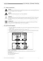
3.2  Connection diagram

The outer shield of the signal cable in the signal converter housing is connected via the strain 
relief terminal.

Bending radius of signal and field current cable: 

 50 mm / 2".

The following illustration is schematic. The positions of the electrical connection terminals 
may vary depending on the type of converter.

DANGER!

All work on the electrical connections may only be carried out with the power disconnected. Take 
note of the voltage data on the nameplate!

DANGER!

Observe the national regulations for electrical installations!

WARNING!

Observe without fail the local occupational health and safety regulations. Any work done on the 
electrical components of the measuring device may only be carried out by properly trained 
specialists. 

INFORMATION!

Look at the device nameplate to ensure that the device is delivered according to your order. 
Check for the correct supply voltage printed on the nameplate.

Figure 3-1: Connection diagram

1  

Electrical terminal compartment in housing of the signal converter for signal and field current cable.

2  

Signal cable

3  

Field current cable C

4  

Connection box for measuring sensor

5  

Functional ground FE

Содержание OPTIPROBE

Страница 1: ...The cost efficient flow indicator OPTIPROBE OPTIPROBE OPTIPROBE OPTIPROBE Quick Start Quick Start Quick Start Quick Start KROHNE 01 2014 4003344001 QS OPTIPROBE R02 en...

Страница 2: ...very 4 2 3 Nameplate 5 2 4 Installation conditions 6 2 4 1 Inlet and outlet 6 2 4 2 Mounting position 6 2 4 3 T section 7 2 4 4 Vibration 7 2 4 5 Magnetic field 7 2 4 6 Pump 7 2 4 7 Control valve 8 2...

Страница 3: ...can result in damage to the device or to parts of the operator s plant INFORMATION These instructions contain important information for the handling of the device CAUTION Installation assembly start u...

Страница 4: ...s of rough handling Report damage to the carrier and to the local office of the manufacturer INFORMATION Do a check of the packing list to make sure that you have all the elements given in the order I...

Страница 5: ...2 Quick Start 3 Factory calibration certificate INFORMATION Look at the device nameplate to ensure that the device is delivered according to your order Check for the correct supply voltage printed on...

Страница 6: ...he side of the pipeline 3 Insert the OPTIPROBE perpendicular 4 Insertion length 25mm 5 DN 80mm CAUTION The OPTIPROBE is a sensor which measures flow speed at one point in the pipe In case the flow spe...

Страница 7: ...1 2014 4003344001 QS OPTIPROBE R02 en 2 4 3 T section 2 4 4 Vibration 2 4 5 Magnetic field 2 4 6 Pump Figure 2 3 Distance after T sections 1 30 DN Figure 2 4 Avoid vibrations Figure 2 5 Avoid magnetic...

Страница 8: ...IPROBE www krohne com 01 2014 4003344001 QS OPTIPROBE R02 en 2 4 7 Control valve 2 4 8 Bends Figure 2 7 Installation before control valve Figure 2 8 Installation in bending pipes Figure 2 9 Installati...

Страница 9: ...9 Open discharge 2 4 10 Temperatures Figure 2 10 Installation before an open discharge 1 Process temperature 2 Ambient temperature CAUTION Protect the device from direct sunlight Temperature range C...

Страница 10: ...OBE unit as far as possible allowed by the chain 4 Close the valve Remind that the volume above the valve is still pressurized 5 Loosen the bolts 2 in picture below to release pressure 6 Dismount the...

Страница 11: ...isconnected Take note of the voltage data on the nameplate DANGER Observe the national regulations for electrical installations WARNING Observe without fail the local occupational health and safety re...

Страница 12: ...sis products Products and systems for the oil gas industry Measuring systems for the marine industry Head Office KROHNE Messtechnik GmbH Ludwig Krohne Stra e 5 47058 Duisburg Germany Tel 49 203 301 0...

Отзывы: