background image

 ELECTRICAL CONNECTIONS 

4

13

H250 M9

www.krohne.com

03/2013 - 4002553501  MA H250/M9-NEPSI Ex i AD R01 en

Electrical connections

4.1  General notes

The connecting cables should be selected according to the applicable installation standards and 
the maximum operating temperature. The outside diameter of the connecting cables must be 
matched to the sealing area of the conduit entry/entries. The connecting cables must be laid and 
fastened securely in such a way that they are adequately protected against damage.
All cores that are not used must be securely connected to the earth potential of the hazardous 
area or carefully insulated against each other and against earth (test voltage 

 500 V

eff

).

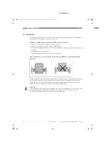
In order to comply with thermal parameters and measuring accuracy, flowmeters for horizontal 
installation are to be installed in the pipeline so that the display is located on the side of the 
measuring tube. The maximum product and ambient temperatures indicated as well as the 
measuring accuracy are based on lateral installation of the display.

Cable entries / Blanking plugs

The variable area flowmeter is equipped with two blanking plugs as standard. These elements 
guarantee protection from foreign bodies and water (protection type) IP65 as per EN 60529. The 
cable entries provided also ensure protection from foreign bodies and water. The nominal 
diameter range of the cable entries is 5...10 mm. Suitable blanking plugs are to be used for 
unused cable entries. Ensure that the seals are tight.

4.2  Power supply

The variable area flowmeter does not require a separate power supply. The required supply for 
the built-in electronics is provided via the 4...20mA current output.

4.3  Inputs/outputs

 The terminal assignment of the built-in electrical equipment is described in the Standard 
Installation and Operation Instructions. The variable area flowmeter signal circuits may only be 
connected to certified intrinsically safe slave units or circuits. For more information see chapter 
"Electrical data"

4.4  Earthing and equipotential bonding

If the device is not sufficiently electrostatically grounded via the process cables, an additional 
earth connection must be established using the ground terminal. The ground terminal on the 
back of the display guarantees an electrostatic connection of the device and does not comply 
with the requirements of an equipotential bonding connection.

Shields should be securely connected to the earth potential of the hazardous area, and 
connected to the terminal located in the indicator part via the shortest route. In the case of shield 
earthing at both ends (e.g. for reasons of electromagnetic compatibility), adequate equipotential 
bonding that reliably prevents potential differences is necessary between the two earthed ends 
of the shield in order to avoid excessive equalising current.

AD_H250_M9_NEPSI_Ex_ia_R01_en_4002553501_PRT.book  Page 13  Thursday, March 7, 2013  7:31 AM

Содержание H250 M9

Страница 1: ...9 H250 M9 H250 M9 H250 M9 Supplementary instructions Supplementary instructions Supplementary instructions Supplementary instructions KROHNE 03 2013 4002553501 MA H250 M9 NEPSI Ex i AD R01 en AD_H250_M9_NEPSI_Ex_ia_R01_en_4002553501_PRT book Page 1 Thursday March 7 2013 7 31 AM ...

Страница 2: ...evice category 6 2 6 Types of protection 6 2 7 Ambient temperature temperature classes 7 2 8 Electrical data 11 3 Installation 12 3 1 Installation 12 4 Electrical connections 13 4 1 General notes 13 4 2 Power supply 13 4 3 Inputs outputs 13 4 4 Earthing and equipotential bonding 13 5 Operation 14 5 1 Start up 14 5 2 Operation 14 6 Service 15 6 1 Maintenance 15 6 2 Dismantling 15 7 Attachment 16 8 ...

Страница 3: ...l Supervision and Inspection Center for Explosion Protection and Safety of Intrumentation in China under Certification No This certification together with its boundary conditions is required to be observed without fail see also Attachment Certificate The Ex marking is NOT acc to the ATEX directive 94 9 EC Placing the product on the market of the EU for purpose of distribution and or use in the EU ...

Страница 4: ...of flow H horizontal orientation U vertical downwards no identifier standard upwards 2 Materials versions RR Stainless steel C PTFE or PTFE ceramics HC Hastelloy Ti Titanium F Sterile version food 3 Heating jacket version B with heating jacket 4 Indicator part series M9 Indicator M9 standard indicator M9S Indicator with increased protection M9R Indicator in stainless steel housing M9T Indicator in...

Страница 5: ...es order item PA order Vxxx product configurator code AC article code Additional plate The association of the housing cover to the device is confirmed by an additional plate with the serial number on the interior of the indicator part 1 Device type 2 Manufacturer 3 Sizing data temperature pressure rating 4 PED data 5 Ex data 6 Electrical connection data 7 Note on observing documentation 8 Manufact...

Страница 6: ...rotection type intrinsic safety protection level ia WARNING Operation with flammable products is only permitted as long as no explosive fuel air mixture builds up on the inside of the flowmeter under operating conditions The operator is responsible for ensuring that the flowmeter is operated safely as regards the temperature and pressure of the products used In case of operation with flammable pro...

Страница 7: ...data of the most unfavourable equipment should be used For certain device version lower values apply due to differing boundary conditions e g lining materials Here the user should consult the technical data sheet INFORMATION The maximum permissible product temperatures listed in the tables are valid under the following conditions The measuring device is installed and operated in accordance with th...

Страница 8: ...mperature range is indicated on the nameplate Ambient temperatures The minimum product temperature is 40 C 40 F Temperature table in C Heating jacket Tm 1 none with HT version Tamb 40 Tamb 60 DN15 DN25 DN15 150 x 236 DN50 DN25 127 x 171 DN80 DN100 DN50 DN80 109 x 145 Temperature table in F Heating jacket Tm 1 none with HT version Tamb 104 Tamb 140 DN15 DN25 DN15 302 x 456 DN50 DN25 260 x 340 DN80 ...

Страница 9: ...00 150 200 150 x 85 85 135 200 200 300 252 K1 K2 64 mW K1 K2 64 mW K1 K2 64 mW K1 K2 64 mW DN15 DN25 DN15 85 100 135 200 200 200 200 x 85 100 135 200 200 300 300 DN50 DN25 85 100 135 200 200 200 200 x 85 100 135 200 200 300 300 DN80 DN100 DN50 DN80 85 100 135 200 200 200 200 x 85 100 135 200 200 300 300 K1 K2 I7S23 5 N SC3 5 N0 169 mW K1 K2 I7S23 5 N SC3 5 N0 169 mW K1 K2 I7S23 5 N SC3 5 N0 169 mW...

Страница 10: ...75 392 302 392 302 x 185 185 275 392 392 572 485 K1 K2 64 mW K1 K2 64 mW K1 K2 64 mW K1 K2 64 mW DN15 DN25 DN15 185 212 275 392 392 392 392 x 185 212 275 392 392 572 572 DN50 DN25 185 212 275 392 392 392 392 x 185 212 275 392 392 572 572 DN80 DN100 DN50 DN80 185 212 275 392 392 392 392 x 185 212 275 392 392 572 572 K1 K2 I7S23 5 N SC3 5 N0 169 mW K1 K2 I7S23 5 N SC3 5 N0 169 mW K1 K2 I7S23 5 N SC3...

Страница 11: ...and ESK2A 24 VDC 25 4 20 mA with HART communication ESK3 PA Profibus transmitter 1 9 24 VDC 12 mA 1 Further information and instructions for operation of the ESK3 PA Profibus transmitter are provided in separate sup plementary instructions Maximum values Built in equipment Ui V Ii mA Pi mW Ci nF Li μH ESKII ESK2A 30 100 1000 20 0 ESK3 PA 1 24 380 5320 0 0 I7S23 5 N SC3 5 N0 16 25 64 150 150 16 52 ...

Страница 12: ...tion with secure footing Take special note of the installation position for the H250 H with horizontal flow direction In order to comply with thermal parameters and measuring accuracy flowmeters for horizontal installation are to be installed in the pipeline so that the display is located on the side of the measuring tube The maximum product and ambient temperatures indicated as well as the measur...

Страница 13: ...er range of the cable entries is 5 10 mm Suitable blanking plugs are to be used for unused cable entries Ensure that the seals are tight 4 2 Power supply The variable area flowmeter does not require a separate power supply The required supply for the built in electronics is provided via the 4 20mA current output 4 3 Inputs outputs The terminal assignment of the built in electrical equipment is des...

Страница 14: ...that they remain within the maximum and minimum permissible temperatures and pressures and the electrical limit values Variable area flowmeters may only be operated if the equipment parts necessary for safety are effective in the long run and are not rendered inoperable during operation Adjusting the limit switch during operation is permitted To do so remove the housing cover Close the housing cov...

Страница 15: ... do this remove the housing cover The housing cover must be closed immediately after the spare parts are exchanged Make sure that the cover seal is properly seated The fastening screws of the housing cover should be tightened with a torque of 1 2 Nm Exchanging the entire device Removal and installation is the user s responsibility Before disconnecting the electric connecting cable of the device it...

Страница 16: ...7 ATTACHMENT 16 H250 M9 www krohne com 03 2013 4002553501 MA H250 M9 NEPSI Ex i AD R01 en Attachment AD_H250_M9_NEPSI_Ex_ia_R01_en_4002553501_PRT book Page 16 Thursday March 7 2013 7 31 AM ...

Страница 17: ...ATTACHMENT 7 17 H250 M9 www krohne com 03 2013 4002553501 MA H250 M9 NEPSI Ex i AD R01 en AD_H250_M9_NEPSI_Ex_ia_R01_en_4002553501_PRT book Page 17 Thursday March 7 2013 7 31 AM ...

Страница 18: ...7 ATTACHMENT 18 H250 M9 www krohne com 03 2013 4002553501 MA H250 M9 NEPSI Ex i AD R01 en AD_H250_M9_NEPSI_Ex_ia_R01_en_4002553501_PRT book Page 18 Thursday March 7 2013 7 31 AM ...

Страница 19: ...ATTACHMENT 7 19 H250 M9 www krohne com 03 2013 4002553501 MA H250 M9 NEPSI Ex i AD R01 en AD_H250_M9_NEPSI_Ex_ia_R01_en_4002553501_PRT book Page 19 Thursday March 7 2013 7 31 AM ...

Страница 20: ...7 ATTACHMENT 20 H250 M9 www krohne com 03 2013 4002553501 MA H250 M9 NEPSI Ex i AD R01 en AD_H250_M9_NEPSI_Ex_ia_R01_en_4002553501_PRT book Page 20 Thursday March 7 2013 7 31 AM ...

Страница 21: ...NOTES 8 21 H250 M9 www krohne com 03 2013 4002553501 MA H250 M9 NEPSI Ex i AD R01 en Notes AD_H250_M9_NEPSI_Ex_ia_R01_en_4002553501_PRT book Page 21 Thursday March 7 2013 7 31 AM ...

Страница 22: ...8 NOTES 22 H250 M9 www krohne com 03 2013 4002553501 MA H250 M9 NEPSI Ex i AD R01 en AD_H250_M9_NEPSI_Ex_ia_R01_en_4002553501_PRT book Page 22 Thursday March 7 2013 7 31 AM ...

Страница 23: ...NOTES 8 23 H250 M9 www krohne com 03 2013 4002553501 MA H250 M9 NEPSI Ex i AD R01 en AD_H250_M9_NEPSI_Ex_ia_R01_en_4002553501_PRT book Page 23 Thursday March 7 2013 7 31 AM ...

Страница 24: ...s industry Measuring systems for the marine industry Head Office KROHNE Messtechnik GmbH Ludwig Krohne Str 5 47058 Duisburg Germany Tel 49 0 203 301 0 Fax 49 0 203 301 10389 info krohne de KROHNE 03 2013 4002553501 MA H250 M9 NEPSI Ex i AD R01 en Subject to change without notice The current list of all KROHNE contacts and addresses can be found at www krohne com AD_H250_M9_NEPSI_Ex_ia_R01_en_40025...

Отзывы: