background image


VS-88DVI - Overview 


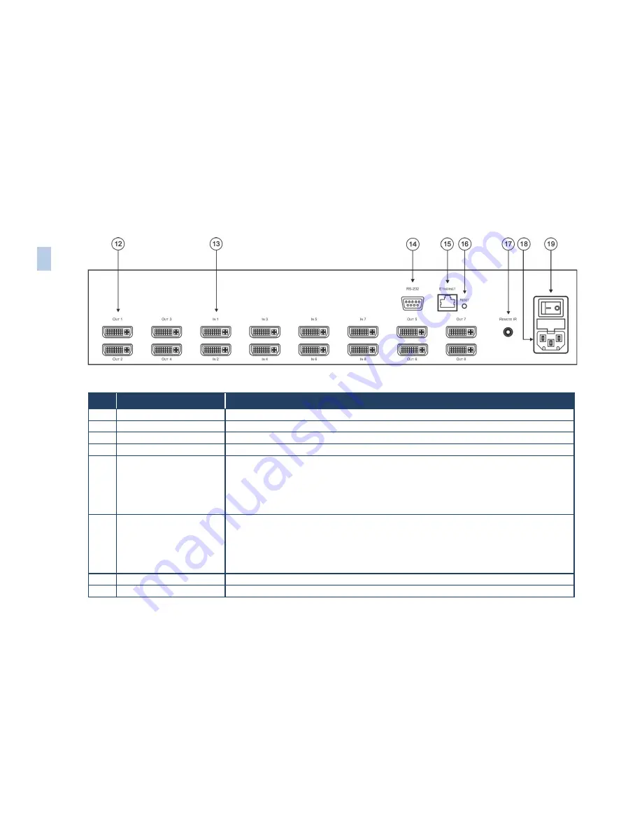
Figure 2: VS-88DVI 8x8 DVI Matrix Switcher Rear Panel 

Feature 

Function 

12 

OUT 

DVI Connectors


Connect to the DVI acceptors (from 1 to 8) 

13 

IN

 DVI Connectors 

Connect to the DVI sources (from 1 to 8) 

14 

RS-232 

9-pin D-sub Port 

Connects to the PC or the RS-232 Remote Controller 

15 

Ethernet 

Connector


Connects to the PC or other Ethernet Controller 

16 

RESET 

Button


Press the reset button to reset to the Ethernet factory default definitions: 
IP number 

 192.168.1.39 

Mask – 255.255.255.0 
Gateway – 192.168.1.1 

First disconnect the power cord and then connect it again while pressing the RESET button. The unit powers 
up and loads its memory with the factory default definitions 

17 

REMOTE IR 

Opening 


Connects to an external IR receiver unit for controlling the machine via an IR remote controller instead 
of using the front panel IR receiver  

Covered by a cap. The 3.5mm connector at the end of the internal IR connection cable fits through this 
opening 

Optional. Can be used instead of the front panel (built-in) IR receiver to remotely control the machine (only if 
the internal IR connection cable has been installed) 

18 

Power Connector with Fuse 

AC connector enabling power supply to the unit 

19 

Power Switch 

Switch for turning the unit ON or OFF 

6


VS
-88D

V

I –

 O

v

er
vi

e

w


Содержание VS-88DVI

Страница 1: ...KRAMER ELECTRONICS LTD USER MANUAL MODEL VS 88DVI 8x8 DVI Matrix Switcher P N 2900 000592 Rev 3...

Страница 2: ......

Страница 3: ...toring and Recalling a Setup 11 6 4 Acquiring the EDID 13 6 5 Connecting the VS 88DVI Using RS 232 15 6 6 Connecting the VS 88DVI Using Ethernet 16 7 Technical Specifications 19 8 Hex Table 20 9 Proto...

Страница 4: ...that are clearly defined by function GROUP 1 Distribution Amplifiers GROUP 2 Switchers and Routers GROUP 3 Control Systems GROUP 4 Format Standards Converters GROUP 5 Range Extenders and Repeaters GRO...

Страница 5: ...rmance Use only good quality connection cables we recommend Kramer high performance high resolution cables to avoid interference deterioration in signal quality due to poor matching and elevated noise...

Страница 6: ...e Electrical and Electronic Equipment WEEE Directive 2002 96 EC aims to reduce the amount of WEEE sent for disposal to landfill or incineration by requiring it to be collected and recycled To comply w...

Страница 7: ...distances I EDIDPro Kramer Intelligent EDID Processing an intelligent EDID handling processing algorithm that ensures Plug and Play operation for DVI systems Flexible control options front panel IR re...

Страница 8: ...nect one or all outputs see Section 6 2 5 SELECT IN Press an INPUT selector button to select an input from 1 to 8 6 SELECT OUT Press an OUTPUT selector button to select an output from 1 to 8 7 STO But...

Страница 9: ...he power cord and then connect it again while pressing the RESET button The unit powers up and loads its memory with the factory default definitions 17 REMOTE IR Opening Connects to an external IR rec...

Страница 10: ...can be located up to 15 meters away from the machine This distance can be extended to up to 60 meters when used with three extension cables Model C A35M A35F 50 Before using the external IR receiver...

Страница 11: ...8 VS 88DVI Installing in a Rack 4 Installing in a Rack This section provides instructions for rack mounting the unit...

Страница 12: ...llustrates do the following 1 Connect up to eight DVI sources for example computer graphics sources to the IN DVI connectors You do not have to connect all the inputs and the outputs 2 Connect the OUT...

Страница 13: ...10 VS 88DVI Connecting the VS 88DVI Figure 3 Connecting the VS 88DVI 8x8 DVI Matrix Switcher...

Страница 14: ...put Press an OUT key followed by an IN key to route this input to that output To route one input to all outputs Press ALL followed by an IN button The input is routed to all outputs 6 2 Disconnecting...

Страница 15: ...etup 2 Press the STO button The STO button flashes 3 Select an OUT or IN SELECT button to store the machine setup for example OUT 5 4 Press the LOCK button to store the current setup In this example t...

Страница 16: ...e the EDID of a new output display 1 Turn ON the VS 88DVI 2 Connect the required acceptor to the output from which you want to acquire the EDID 3 Press the EDID and STO buttons simultaneously and hold...

Страница 17: ...the first EDID is copied The selected input number 1 flashes on the display Press the SELECT OUT 1 button from which the EDID is acquired Press the SELECT IN 1 button again The IN 1 button ceases to...

Страница 18: ...u can connect to the unit via a crossed RS 232 connection using for example a PC A crossed cable or null modem is required as shown in method A and B respectively If a shielded cable is used connect t...

Страница 19: ...for connection via a network hub or network router After connecting the Ethernet port you have to install and configure your Ethernet Port For detailed instructions see the Ethernet Configuration FC...

Страница 20: ...ing the VS 88DVI 17 Figure 6 Local Area Connection Properties Window 6 Select Use the following IP Address and fill in the details as shown in Figure 7 7 Click OK Figure 7 Internet Protocol TCP IP Pro...

Страница 21: ...S 88DVI to the Ethernet port on a network hub or network router via a straight through cable with RJ 45 connectors 6 6 3 Control Configuration via the Ethernet Port To control several units via the Et...

Страница 22: ...upports DVI 1 1 MAX RESOLUTION Up to UXGA 1080p 1920x1200 CONTROLS Front panel buttons Infrared remote control transmitter RS 232 Ethernet POWER CONSUMPTION 100 240VAC 50 60Hz 43VA OPERATING TEMPERATU...

Страница 23: ...01 83 87 81 01 83 86 81 01 83 85 81 01 83 84 81 01 83 83 81 01 83 82 81 01 83 81 81 IN 3 01 84 88 81 01 84 87 81 01 84 86 81 01 84 85 81 01 84 84 81 01 84 83 81 01 84 82 81 01 84 81 81 IN 4 01 85 88 8...

Страница 24: ...defined according to the table below INSTRUCTION NO is the value set in N5 N0 2nd Byte Bit 7 Defined as 1 I6 I0 INPUT When switching i e instruction codes 1 and 2 the 7 bit INPUT is set as the input n...

Страница 25: ...13 62 DEFINE MACHINE 1 Number of inputs 2 Number of outputs 3 Number of setups 1 For video 2 For audio 3 For SDI 4 For remote panel 5 For RS 422 controller 6 For control data 14 NOTES on the above ta...

Страница 26: ...ly to the request to send the version number would be HEX code 7D 83 85 81 i e 128dec 3dec for 2nd byte 128dec 5dec for 3rd byte If the OUTPUT is set as 1 then the ASCII coding of the lettering follow...

Страница 27: ......

Страница 28: ...sit our Web site where updates to this user manual may be found We welcome your questions comments and feedback Web site www kramerelectronics com E mail info kramerel com P N 2900 000592 Rev 3 SAFETY...

Отзывы: