background image

KRAMER:  SIMPLE CREATIVE TECHNOLOGY


Connecting the VS-808DS 


12

6.3  Setting the VS-808DS Dipswitches 

This section describes the machine set-up and dipswitch selection.  
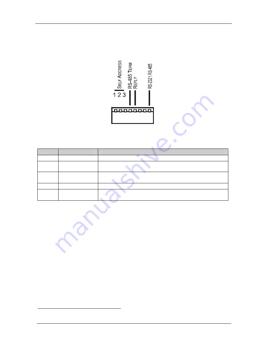
Figure 5 and Table 3 define the factory default dipswitches. 


Figure 5: VS-808DS Dipswitches 

Table 3: Dipswitch Settings 

DIPS 

Function 

Description 

1, 2, 3 

SELF ADDRESS 

Determines the position of the machine in the input expansion configuration 

RS-485 TERM 

ON for RS-485 Line Termination 

OFF for no RS-485 Line Termination 

REPLY 

ON enables reply from switcher to PC 
OFF disables reply from switcher to PC 

6, 7 

RESERVED 


RS-232 \ RS-485 

ON enables RS-232 communication between switcher and PC 
OFF disables reply from switcher to PC 

6.3.1 

Setting the SELF ADDRESS Dipswitches 

The SELF ADDRESS determines the position of a 

VS-808DS

 unit in the 

sequence, specifying which 

VS-808DS

 unit is being controlled when several 

VS-808DS

 units are controlled by a PC or serial controller. Set the SELF 

ADDRESS on a 

VS-808DS

 unit via DIPS 1, 2, and 3, according to Table 4. 


When using a stand-alone 

VS-808DS

 unit, set the SELF ADDRESS to 1 


When connecting more than one 

VS-808DS

 unit, set the first 

machine (the Master) connected via RS-232, as SELF ADDRESS # 

1. The Master connects to the PC via the RS-232 port. The other 

VS-808DS

  slave units (each set

1

 to a SELF ADDRESS # between 2 

and 8) interconnect via their RS-485 ports to the RS-485 port on the 

Master 


1 You do not have to number the units in the sequence order as they connect to the PC 

Содержание VS-808DS

Страница 1: ...Kramer Electronics Ltd USER MANUAL Model VS 808DS 8x8 Video Audio Matrix Switcher Scaler...

Страница 2: ...Follow Video Option 15 7 3 2 Setting the Breakaway Option 15 7 4 Confirming Settings 15 7 4 1 Toggling between the At Once and Confirm Modes 16 7 4 2 Confirming a Switching Action 16 7 5 Storing Reca...

Страница 3: ...ures 5 Table 2 VS 808DS 8x8 Video Audio Matrix Switcher Scaler Rear Panel Features 6 Table 3 Dipswitch Settings 12 Table 4 Self Address Dipswitch Settings 13 Table 5 Technical Specifications of the VS...

Страница 4: ...emote control transmitter including the required batteries and a separate user manual3 and this user manual3 2 Getting Started We recommend that you Unpack the equipment carefully and save the origina...

Страница 5: ...KRAMER SIMPLE CREATIVE TECHNOLOGY Getting Started 2 Video Player Video Recorder LCD Display...

Страница 6: ...via an external remote IR receiver optional3 and remotely by RS 485 or RS 232 serial commands transmitted by a touch screen system PC or other serial controller Scaled graphics output resolutions VGA...

Страница 7: ...KRAMER SIMPLE CREATIVE TECHNOLOGY Your VS 808DS 8x8 Video Audio Matrix Switcher Scaler 4 Figure 1 VS 808DS 8x8 Video Audio Matrix Switcher Scaler Front Panel...

Страница 8: ...e inputs an OFF ALL combination disconnects all the outputs 9 TAKE Button Pressing TAKE toggles the mode between the Confirm mode2 and the At Once mode user confirmation per action is unnecessary When...

Страница 9: ...Terminal Block Port Pin G is for Ground connection 1 Pins B and A are for RS 485 25 RS 232 DB 9F Port Connects to the PC or the Remote Controller 26 SCALER OUTPUT HD15 Connector Connects to the video...

Страница 10: ...Installing on a Rack 7 5 Installing on a Rack This section describes what to do before installing on a rack and how to rack mount...

Страница 11: ...CA connectors to up to eight composite video acceptors for example composite video recorders TV and so on 3 Connect a PC and or controller to the RS 232 port see section 6 1 4 Connect3 the SCALER OUT...

Страница 12: ...Connecting the VS 808DS 9 Figure 2 Connecting the VS 808DS 8x8 Video Audio Matrix Switcher Scaler...

Страница 13: ...onnect the Null modem adapter with a 9 wire flat cable to the RS 232 DB9 port on your PC To connect without using a Null modem adapter Connect the RS 232 DB9 port on your PC to the RS 232 DB9 rear pan...

Страница 14: ...ar panel port of the VS 808DS unit Connect the B PIN on the RS 485 rear panel port of the RC 3000 to the B PIN on the RS 485 rear panel port of the VS 808DS unit If shielded twisted pair cable is used...

Страница 15: ...witcher and PC OFF disables reply from switcher to PC 6 3 1 Setting the SELF ADDRESS Dipswitches The SELF ADDRESS determines the position of a VS 808DS unit in the sequence specifying which VS 808DS u...

Страница 16: ...the controlling device knows that the controlled device has carried out its instructions When an RS 485 connection is used for communication between the Matrix Switcher and the PC dipswitch 8 should...

Страница 17: ...ter switching on the power and When simultaneously pressing and holding for 3 seconds the INPUT buttons 1 2 and 3 see section 7 6 7 2 Selecting and Connecting an Output and or Input To switch an input...

Страница 18: ...on The audio will follow the video 7 3 2 Setting the Breakaway Option To set the Breakaway option Press either the AUDIO for audio control only or the VIDEO for video control only button If the AUDIO...

Страница 19: ...s 7 4 2 Confirming a Switching Action To confirm a switching action in the Confirm mode do the following 1 Press an OUTPUT INPUT combination The corresponding input number that is displayed in the STA...

Страница 20: ...Press the RCL button The RCL button blinks 2 Press the appropriate INPUT SELECTOR button the INPUT SELECTOR button corresponding to the setup The memory recalls the stored data from that reference 7 5...

Страница 21: ...UT RESOLUTIONS VGA 640 x 480 SVGA 800x600 XGA 1024x768 WXGA 1366x 768 SCALED OUTPUT REFRESH RATE 60Hz MAX OUTPUT LEVEL VIDEO 2 2Vpp CV 0 77Vpp XGA AUDIO 22dBm BANDWIDTH 3dB VIDEO 200MHz AUDIO 100kHz D...

Страница 22: ...e of Hex Codes for the Master VS 808DS Table 6 shows the HEX codes for switching the master VS 808DS Table 6 Hex Codes for Switching the Master VS 808DS 8 7 6 5 4 3 2 1 OUT IN 1 IN 2 IN 3 8 7 6 5 IN 4...

Страница 23: ...e below INSTRUCTION NO is the value to be set for N5 N0 2nd BYTE Bit 7 Defined as 1 I6 I0 INPUT When switching ie instruction codes 1 and 2 the INPUT 7 bits is set as the input number which is to be s...

Страница 24: ...byte 8 User defined sync 32 RGBHV seamless switching 64 Set for delayed switch 65 Execute delayed switch 66 Cancel delayed switch setting 2 5 17 18 0 0 audio follow video 1 audio breakaway 2 8 BREAKAW...

Страница 25: ...trast 3 decrease contrast 4 increase brightness 5 decrease brightness 6 increase colour 7 decrease colour 8 increase hue 9 decrease hue 16 increase H phase 17 decrease H phase 18 increase V position 1...

Страница 26: ...XTENDED DATA 7 MSBs for INPUT data 7 MSBs for OUTPUT data 20 NOTES on the above table NOTE 1 When the master switcher is reset e g when it is turned on the reset code is sent to the PC If this code is...

Страница 27: ...is programmable NOTE 12 Under normal conditions the machine s present status is saved each time a change is made The power down save auto save may be disabled using this code Note that whenever the ma...

Страница 28: ...ex you would first send HEX codes 3F 80 85 81 and then send HEX codes 16 83 A9 81 To set the audio gain of output 6 to 10013dec 271Dhex first send HEX codes 3F 80 CE 81 followed by HEX codes 16 86 9D...

Страница 29: ...KRAMER SIMPLE CREATIVE TECHNOLOGY 26...

Страница 30: ...or the latest information on our products and a list of Kramer distributors visit our Web site www kramerelectronics com where updates to this user manual may be found We welcome your questions commen...

Отзывы: