background image

Kramer Protocol 2000 


29

12  Kramer Protocol 2000

1


The 

VS-4x4YCxl

 is compatible with Kramer’s Protocol 2000 (version 0.42) 

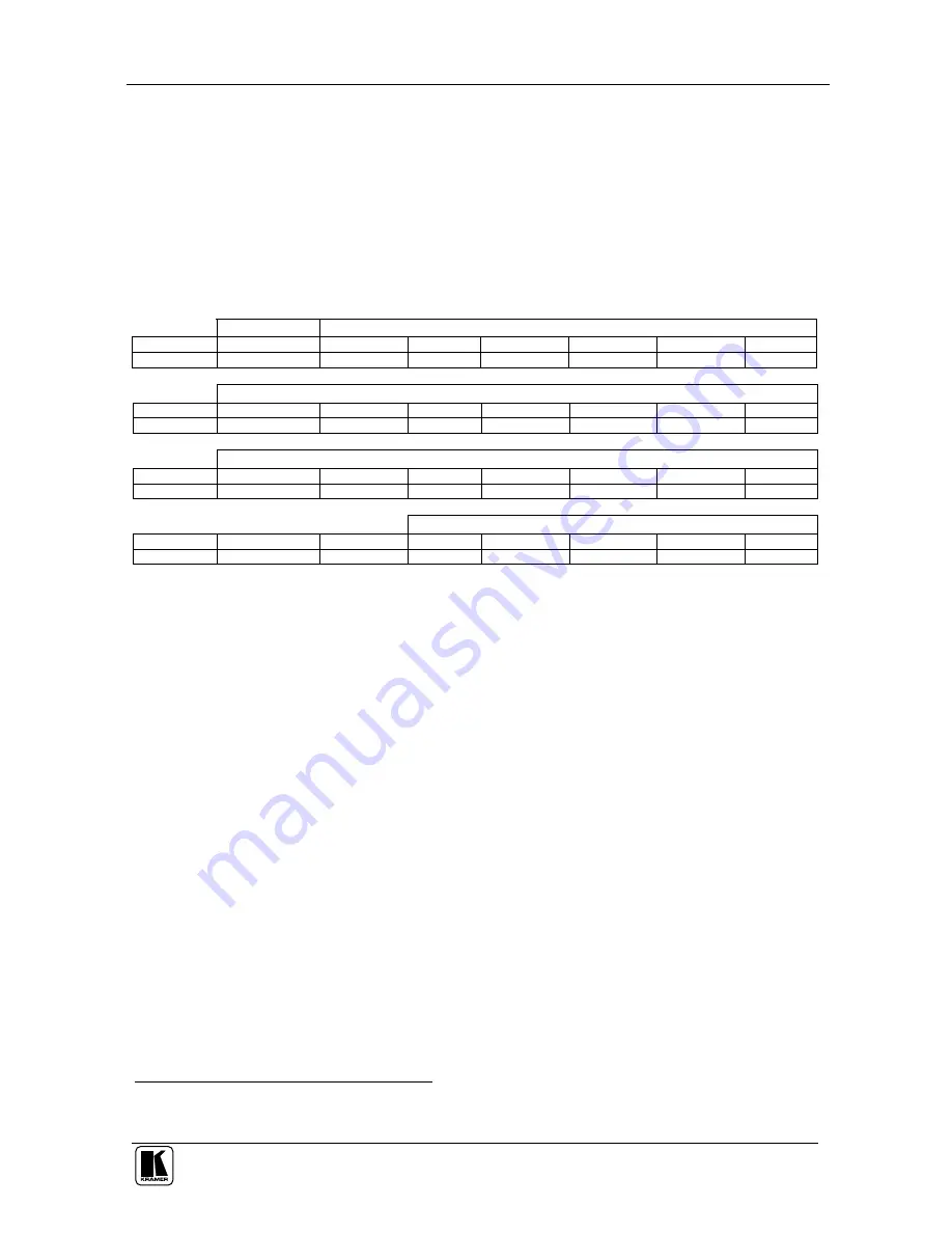
(below). This RS-232 / RS-485 communication protocol uses four bytes of 

information as defined below. For RS-232, a null-modem connection between 

the machine and controller is used. The default data rate is 9600 baud, with 

no parity, 8 data bits and 1 stop bit. 

Table 8: Protocol Definitions 

MSB 


LSB 


DESTINATION 

INSTRUCTION 

N5 

N4 

N3 

N2 

N1 

N0 

1st byte 


INPUT 

I6 

I5 

I4 

I3 

I2 

I1 

I0 

2nd byte 


OUTPUT 

O6 

O5 

O4 

O3 

O2 

O1 

O0 

3rd byte 


MACHINE NUMBER 

OVR 

M4 

M3 

M2 

M1 

M0 

4th byte 


1st BYTE:  Bit 7 – Defined as 0. 

D – “ DESTINATION” : 

0 - for sending information to the switchers (from the PC); 

1 - for sending to the PC (from the switcher). 

N5…N0 – “ INSTRUCTION”  

The function that is to be performed by the switcher(s) is defined by the INSTRUCTION (6 bits). Similarly, if a function is 

performed  via  the  machine’s  keyboard,  then  these  bits  are  set  with  the  INSTRUCTION  NO.,  which  was  performed.  The 

instruction codes are defined according to the table below (INSTRUCTION NO. is the value to be set for N5…N0). 


2nd BYTE:  Bit 7 – Defined as 1. 


I6…I0 – “ INPUT” . 

When  switching  (ie.  instruction  codes  1  and  2),  the  INPUT  (7  bits)  is  set  as  the  input  number  which  is  to  be  switched. 

Similarly, if switching is done via the machine’s front-panel, then these bits are set with the INPUT NUMBER which was 

switched. For other operations, these bits are defined according to the table. 


3rd BYTE:  Bit 7 – Defined as 1. 

                    O6…O0 – “ OUTPUT” . 

When switching (i.e. instruction codes 1 and 2), the OUTPUT (7 bits) is set as the output number which is to be switched. 

Similarly, if switching is done via the machine’s front-panel, then these bits are set with the OUTPUT NUMBER which was 

switched. For other operations, these bits are defined according to the table. 


4th BYTE:   Bit 7 – Defined as 1.  


Bit 5 – Don’t care.  


OVR – Machine number override. 


M4…M0 – MACHINE NUMBER. 

Used to address machines in a system via their machine numbers. When several machines are controlled from a single serial 

port, they are usually configured together with each machine having an individual machine number.  

If the OVR bit is set, then all machine numbers will accept (implement) the command, and the addressed machine will reply. 

For  a  single  machine  controlled  via  the  serial  port,  always  set  M4…M0  =  1,  and  make  sure  that  the  machine  itself  is 

configured as MACHINE NUMBER = 1.  


1  You  can  download  our  user-friendly  “ Software  for  Calculating  Hex  Codes  for  Protocol  2000”   from  our  Web  site: 
http://www.kramerelectronics.com 

Содержание VS-4x4YCx1

Страница 1: ...Kramer Electronics Ltd USER MANUAL Model VS 4x4YCxl 4x4 s Video Audio Matrix Switcher ...

Страница 2: ...tion 15 7 3 Switching OUT IN Combinations 15 7 4 Confirming Settings 15 7 4 1 Toggling between the AT ONCE and CONFIRM Modes 16 7 4 2 Confirming a Switching Action 16 7 5 Storing Recalling Input Output Configurations 17 7 5 1 Storing an Input Output Configuration 17 7 5 2 Recalling an Input Output Configuration 17 7 5 3 Deleting an Input Output Configuration 18 7 6 Locking the Front Panel 18 7 7 A...

Страница 3: ... Unit Characteristics 14 Figure 12 Storing and Recalling using the Input Output Buttons 17 Figure 13 Splash Screen 20 Figure 14 Atmel Flip Window 20 Figure 15 Device Selection Window 21 Figure 16 Device Selection window 21 Figure 17 Loading the Hex 22 Figure 18 RS 232 Window 22 Figure 19 Atmel Flip Window Connected 23 Figure 20 Atmel Flip Window Operation Completed 23 Tables Table 1 Front Panel VS...

Страница 4: ...udio Matrix Switcher Power cord Null modem adapter Windows based Kramer control software2 Infra red remote control transmitter including the required battery and a separate user manual3 This user manual3 2 Getting Started We recommend that you Unpack the equipment carefully and save the original box and packaging materials for possible future shipment Review the contents of this user manual Use Kr...

Страница 5: ...ise switch control Lock button to prevent tampering with the front panel The ability to control via the front panel buttons via the Infra red remote control transmitter and remotely by RS 485 or RS 232 serial commands transmitted by a touch screen system PC or other serial controller To achieve the best performance Connect only good quality connection cables thus avoiding interference deterioratio...

Страница 6: ...O AFV LOCK STO TAKE RCL AUDIO VIDEO AUDIO VIDEO OUT 4 OUT 2 SYNC IN 4 IN 2 IN 3 IN 1 G G L L 2 2 R R G G L L 3 3 R R G G L L 4 4 R RS 232 RS 485 FLASH PROG G B A OUTPUTS INPUTS 100 240 VAC 50 60 Hz G G L L 1 1 R R IN 1 EXT OUT 3 OUT 1 R MACH RS 485 TERM Figure 1 VS 4x4YCxl 4x4 s Video Audio Matrix Switcher ...

Страница 7: ...e video channels 11 AUDIO Button When pressed 6 actions relate to audio 12 STO STORE Button Pressing STO followed by an output button stores the current setting 7 13 RCL RECALL Button Pressing the RCL button and the corresponding OUTPUT key recalls a setup from the non volatile memory The stored status blinks Pressing a different OUTPUT button lets you view8 another setup After making your choice ...

Страница 8: ...ches Dipswitches for setup of the unit 1 2 3 and 4 are for setting the Machine 8 is for RS 485 Termination 8 RS 232 DB 9F Port Connects to the PC or the Remote Controller 9 FLASH PROG Button Push in 3 for Program to upgrade to the latest Kramer firmware see section 8 or release for Normal the factory default 4 10 RS 485 Terminal Block Port Pin G is for Ground connection Pins B and A are for RS 485...

Страница 9: ...section describes how to connect the VS 4x4YCxl In particular how to Connect the VS 4x4YCxl rear panel see section 5 1 Control via RS 232 for example using a PC see section 5 2 Control via RS 485 see section 5 3 Connect the audio inputs outputs see section 5 4 Set the dipswitches see section 5 5 ...

Страница 10: ...4x4YCxl 4x4 s Video Audio Matrix Switcher 1 Switch OFF the power on each device before connecting it to your VS 4x4YCxl After connecting your VS 4x4YCxl switch on its power and then switch on the power on each device DO NOT push in the rear panel Flash Program Program button item 9 in Table 2 and DO NOT push in the underside Flash Program Reset button These are only used for upgrade to the latest ...

Страница 11: ... Master VS 4x4YCxl unit to the Null modem adapter and connect the Null modem adapter with a 9 wire flat cable to the RS 232 DB9 port on your PC To connect a PC to the VS 4x4YCxl unit without using a Null modem adapter Connect the RS 232 DB9 port on your PC to the RS 232 DB9 rear panel port on the Master VS 4x4YCxl unit as Figure 4 illustrates depending on whether the PC has a 9 pin or 25 pin conne...

Страница 12: ...YCxl unit If shielded twisted pair cable is used the shield may be connected to the G Ground PIN on one of the units for example on the RC 3000 2 Set the VS 4x4YCxl unit as MACHINE 1 according to Table 4 that is DIP 1 DIP 2 DIP 3 and DIP 4 OFF and set the other dipswitches on the VS 4x4YCxl unit as follows Set DIP 5 DIP 6 and DIP 7 OFF Set Dip 8 ON for RS 485 Line Termination with 120 KEYBOARD EXT...

Страница 13: ...to wire a balanced input output connection Figure 6 Connecting the Balanced Stereo Audio Input Output Figure 7 illustrates how to wire an unbalanced input Figure 7 Connecting the Unbalanced Stereo Audio Input Figure 8 illustrates how to wire an unbalanced acceptor to the balanced output of the unit Figure 8 Connecting the Unbalanced Stereo Audio Output ...

Страница 14: ... is being controlled when several VS 4x4YCxl units connect to a PC or serial controller Set the MACHINE on a VS 4x4YCxl unit via DIPS 1 2 3 and 4 according to Table 4 When using a stand alone VS 4x4YCxl unit set the MACHINE to 1 When connecting more than one VS 4x4YCxl unit set the first machine the Master that is closest to the PC as MACHINE 11 Table 4 Machine Dipswitch Settings DIPSWITCH DIPSWIT...

Страница 15: ...S 4x4YCxl unit to the PC using the Null modem adapter provided with the machine recommended as section 5 2 describes 3 Connect the RS 485 terminal block port on the first VS 4x4YCxl unit to the RS 485 port on the second VS 4x4YCxl unit and so on connecting all the RS 485 ports 4 Set the dipswitches as section 5 5 describes In particular Set the first VS 4x4YCxl unit as MACHINE 1 and the following ...

Страница 16: ...Controlling via RS 232 and RS 485 13 Figure 10 Cascading Individual Units in a Control Configuration via RS 232 and RS 485 ...

Страница 17: ... 3 INPUTS buttons1 1 2 and 3 for 3 seconds The following information is displayed in the 7 segment Displays The number of IN and OUT ports2 The firmware version number and the MACHINE 3 Figure 11 VS 4x4YCxl Unit Characteristics 7 2 Choosing the Audio Follow Video or Breakaway Option You can switch stereo audio signals in one of 2 ways either Audio follow video AFV in which all operations and statu...

Страница 18: ...he Audio section If the VIDEO button illuminates all switching operations relate to the Video section 7 3 Switching OUT IN Combinations To switch a video audio input to a video audio output do the following 1 Press an OUT button either 1 2 3 4 or ALL The corresponding Audio and2 or Video 7 segment Displays blink 2 Press an IN button either 1 2 3 4 or OFF The selected input switches to the selected...

Страница 19: ...IRM mode in which the TAKE button illuminates Actions now require user confirmation and the TAKE button illuminates 2 Press the illuminated TAKE button to toggle from the CONFIRM mode back to the AT ONCE mode Actions no longer require user confirmation and the TAKE button no longer illuminates 7 4 2 Confirming a Switching Action To confirm a switching action in CONFIRM mode do the following 1 Pres...

Страница 20: ...RM mode press the blinking TAKE button to confirm the action The memory stores the data at that reference 7 5 2 Recalling an Input Output Configuration To recall an input output configuration do the following 1 Press the RCL button The RCL button blinks 2 Press the appropriate Input Output button the button corresponding to the setup If in the CONFIRM mode that setup configuration will blink in th...

Страница 21: ...he LOCK button for more than two seconds until the LOCK button is illuminated The front panel is locked Pressing a button will have no effect except to cause the LOCK button to blink3 To unlock the VS 4x4YCxl Press the illuminated LOCK button for more than two seconds until the LOCK button is no longer illuminated The front panel unlocks 7 7 Adjusting the Audio Gain Control You can adjust the gain...

Страница 22: ...tion 2 Extract the file FLIP_VS4x4YCxl zip to a folder for example C Program Files Kramer Flash 3 Create a shortcut on your desktop to the file FLIP EXE 8 2 Connecting the PC to the RS 232 Port Before installing the latest Kramer firmware version on a VS 4x4YCxl unit do the following 1 Connect the RS 232 DB9 rear panel port on the VS 4x4YCxl unit to the Null modem adapter and connect the Null mode...

Страница 23: ...IP EXE The Splash screen appears as follows Figure 13 Splash Screen 2 After a few seconds the Splash screen is replaced by the Atmel Flip window Figure 14 Atmel Flip Window 3 Press the keyboard shortcut key F2 or select the Select command from the Device menu or press the integrated circuit icon in the upper right corner of the window The Device Selection window appears ...

Страница 24: ... Figure 15 Device Selection Window 4 Click the button next to the name of the device and select from the list AT89C51RD2 AT89C51RD2 T89C51RD2 Figure 16 Device Selection window 5 Click OK and select Load Hex from the File menu ...

Страница 25: ... 7 Press the keyboard shortcut key F3 or select the Communication RS232 command from the Settings menu or press the keys Alt SCR The RS232 window appears Change the COM port according to the configuration of your computer and select the 9600 baud rate Figure 18 RS 232 Window 8 Click Connect In the Atmel Flip window in the Operations Flow column the Run button is active and the name of the chip app...

Страница 26: ...of the operation is completed the check box for that stage becomes colored green 1 When the operation is completed all 4 check boxes will be colored green and the status bar message Memory Verify Pass appears 2 VS4X4YCXL hex Figure 20 Atmel Flip Window Operation Completed 1 See also the blue progress indicator on the status bar 2 If an error message Not Finished shows click Run again ...

Страница 27: ...Bm 25k on detachable terminal blocks OUTPUTS 4 s Video 1 Vpp 75 Y 0 3Vpp 75 C on 4p connectors 4 balanced stereo audio 4dBm 47 on detachable terminal blocks MAX OUTPUT LEVEL VIDEO 2 5Vpp AUDIO 19dBm BANDWIDTH 3dB VIDEO 75MHz Fully Loaded AUDIO 28kHz DIFF GAIN 0 02 DIFF PHASE 0 02 Deg K FACTOR 0 05 S N RATIO VIDEO 82dB AUDIO 74dB CROSSTALK all hostile VIDEO 61dB 5MHz AUDIO 70dB 20kHz CONTROLS Audio...

Страница 28: ...ex Codes for Audio Input Output Gain Control Sections 11 1 and 11 2 contain the tables of hex codes for input and output signal gain control adjustment respectively 11 1 Tables of Hex Codes for Audio Input Gain Control Before adjusting the audio inputs gain instruction 42 the AUDIO PARAMETER SETTINGS FOR INSTRUCTIONS 22 24 25 is sent1 2A 86 80 81 This command is sent once and the audio inputs gain...

Страница 29: ...6 0 1 Instruction 22 Audio Level 2 16 2 16 2 2 16 3 2 16 4 2 16 0 2 Instruction 22 Audio Level 127 16 FF 16 2 FF 16 3 FF 16 4 FF 16 0 FF Instruction 63 F F F F F Instruction 22 Audio Level 128 16 0 16 2 0 16 3 0 16 4 0 16 0 0 Instruction 63 F 0 F 0 F 0 F 0 F 0 Instruction 22 Audio Level 216 1 1 16 D8 16 2 D8 16 3 D8 16 4 D8 16 0 D8 Instruction 63 3F 0 3F 0 3F 0 3F 0 3F 0 Instruction 22 Audio Level...

Страница 30: ...nstruction 42 the AUDIO PARAMETER SETTINGS FOR INSTRUCTIONS 22 24 25 is sent1 2A 87 80 81 The command is sent once and the audio outputs gain adjustment mode continues until instruction 42 changes to the audio inputs gain adjustment mode Table 7 lists the Hex values for the audio gain control of the 4 outputs 1 See Protocol 2000 description in section 12 ...

Страница 31: ...tput is physically disconnected from the input Instruction 22 Audio Level 2 16 2 16 2 2 16 3 2 16 4 2 16 0 2 Instruction 22 Audio Level 127 16 FF 16 2 FF 16 3 FF 16 4 FF 16 0 FF Instruction 63 F F F F F Instruction 22 Audio Level 128 16 0 16 2 0 16 3 0 16 4 0 16 0 0 Instruction 63 F 0 F 0 F 0 F 0 F 0 Instruction 22 Audio Level 216 1 1 16 D8 16 2 D8 16 3 D8 16 4 D8 16 0 D8 Instruction 63 3F 0 3F 0 ...

Страница 32: ...I0 INPUT When switching ie instruction codes 1 and 2 the INPUT 7 bits is set as the input number which is to be switched Similarly if switching is done via the machine s front panel then these bits are set with the INPUT NUMBER which was switched For other operations these bits are defined according to the table 3rd BYTE Bit 7 Defined as 1 O6 O0 OUTPUT When switching i e instruction codes 1 and 2 ...

Страница 33: ...ST BREAKAWAY SETTING Set as SETUP or set to 126 or 127 to request if machine has this function 0 Request audio breakaway setting 1 Request FOLLOW setting 3 4 6 15 12 REQUEST VIDEO AUDIO TYPE SETTING Set as SETUP or set to 126 or 127 to request if machine has this function 0 for video 1 for audio 3 4 6 15 REQUEST WHETHER SETUP IS DEFINED Set as SETUP 0 8 16 ERROR BUSY 0 0 error 1 invalid instructio...

Страница 34: ...he current setting of this function even for the case that the function is not defined For example for a video switcher which always switches during the VIS of input 1 and its VIS setting cannot be programmed otherwise the reply to the HEX code 0A FE 80 81 i e request VIS setting with INPUT set as 126dec would be HEX codes 4A FE 81 81 i e VIS setting 1 which is defined as VIS from input 1 NOTE 7 S...

Страница 35: ...ed after implementation of the switch if the execute command is used For example to connect input 4 to output 3 after a delay send HEX codes 07 80 C0 81 set for delayed switch 01 84 83 81 switch code then after the required delay send HEX codes 07 80 C1 81 execute delayed switch to implement the switch NOTE 18 After this instruction is sent the unit will respond to the ASCII command set The ASCII ...

Страница 36: ...original dated invoice or a copy must be presented as proof of warranty coverage and should be included in any shipment of the product Please also include in any mailing a contact name company address and a description of the problem s 3 For the name of the nearest Kramer authorized service center consult your authorized dealer LIMITATION OF IMPLIED WARRANTIES All implied warranties including warr...

Страница 37: ...mail info kramerel com P N 2900 002107 REV 2 For the latest information on our products and a list of Kramer distributors visit our Web site www kramerelectronics com where updates to this user manual may be found We welcome your questions comments and feedback ...

Отзывы: