


Kramer Electronics Ltd.
12
5.6
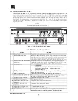
Getting to Know Your FC-4043
The KRAMER FC-4043 CV/YC - Component Transcoder interfaces between Composite video and Y/C to the
most widely used professional video format - Component Video (Y, R-Y, B-Y) bi-directionally. In many video
studios and production centers there is a need to convert from one format to the other, and the Kramer FC-4043
is the perfect choice as it operates in the most common standards - PAL, SECAM and NTSC (both) – and bi-
directionally. Decoding operation is microprocessor controlled via the internal I
2
C bus and the machine allows
standards conversion between PAL and SECAM. Front/Rear panel features of the FC-4042 are described in
Figure
6
and Table
7
.
NOTE
For operation instructions refer to section 9.
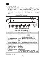
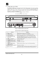
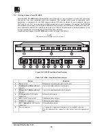
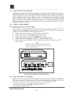
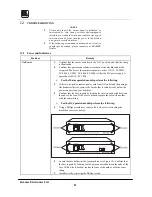
Figure
6
: FC-4043 Front/Rear Panel Features
Table
7
: FC-4043 - Front/Rear Panel Features
No.
Feature Function
1.
Power Switch
Illuminated switch supplies power to the unit.
2.
ENC/TRANS pushbutton
Encoder or Transcoder function selector. When Transcoder is selected (switch
is not illuminated), an internal link is formed between the components outputs
of the Decoder section and the component inputs of the Encoder section –
allowing for example - Composite SECAM to PAL conversion (or vice versa)
3.
PAL, SECAM, 3.58, 4.43 encoder
pushbuttons
Illuminated pushbuttons: selecting the output encoding standard desired.
Note that the machine does not scan convert between PAL and NTSC but can
allow for NTSC 4.43 output from an NTSC 3.58 input for example.
4.
Internal trimmers
Not used.
WARNING
!
Adjustments or attempted adjustments of the trimmers are
not allowed. Failure to comply with this warning may
damage the machine.
5.
CV/YC pushbutton
Illuminated pushbutton. Selects either composite video or Y/C signal at the
decoder input when pressed.
6.
HUE (+/-) pushbuttons
Only active when NTSC is used, for changing output picture hue.
7.
PAL, SECAM, 3.58, 4.43 LEDS
Illuminates the appropriate LED when one of the corresponding standards
input signal is auto detected (blinks when there is no input.)
8.
INPUTS CV BNC connector
Composite video input to the Decoder.
9.
INPUTS Y/C 4P connector Y/C input to the Decoder.
10.
OUTPUTS Y, R-Y, B-Y BNC
connectors
Component video outputs from the Decoder.
11.
INPUTS Y, R-Y, B-Y BNC
connectors
Component video inputs to the Encoder.
12.
OUTPUTS YC 4P connector YC output from the Encoder.
13.
OUTPUTS CV BNC connector
Composite video output from the Encoder.
14.
Power Connector
A 3-prong AC connector allows power to be supplied to the unit. Directly
underneath this connector, a fuse holder houses the appropriate fuse.


