


Kramer Electronics Ltd.
9
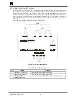
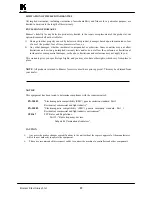
Figure 5: VGA/XGA Switching
8.3
Typical Video Switching
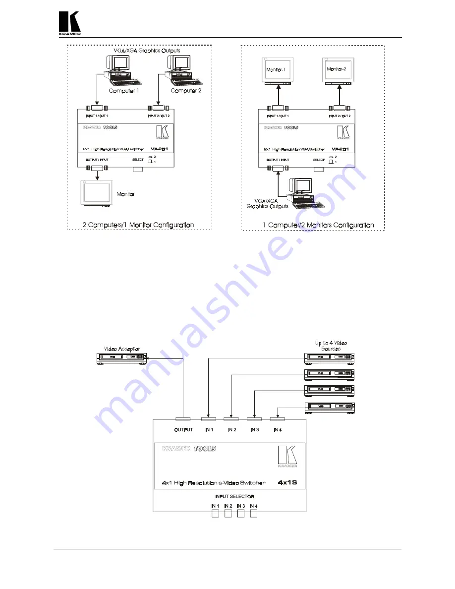
Figure 6 illustrates a typical video setup of the mechanical switchers: the incoming input signals from four
sources (VCRs in this case) are switched to one output, connected to one acceptor. Control over the
switched input is implemented by the input selectors located on the side panel of the machine (4x1S in this
case). Perform the following steps (as necessary):
1) Connect the output of the video sources to the video inputs of the 4x1S.
2) Connect the output of the 4x1S to the input of a video acceptor.
3) Select the required video input to be switched, using front panel input selector pushbuttons.
Figure 6: Typical Video Switching


