


Korenix JetNet 3500 Series Industrial Unmanaged Redundant Ethernet Rail Switch User’s
Manual
2-10
5. PWR1 and PWR2 dual power inputs can be connected to power sources simultaneously.
When the primary power source fails (the default setting is PWR1), the system will
automatically switch to the secondary power source (PWR2), preventing any power
interruption.
6. Check the LED for PWR1 and PWR2 to make sure that your JetNet is operating normally.
Note
: If you are using DC IN power jack to supply power to the JetNet, please check the PWR
LED.
7. Use Category 5 straight through Ethernet cables with RJ45 connectors to connect network
devices.
8. Connect one side of an Ethernet cable with a RJ45 connector to the JetNet’s Ethernet port
(RJ-45 port), and the other side of the Ethernet cable to the network device’s Ethernet port
(RJ-45 port).
Note
: Make sure that the connected network switches support MDI/MDI-X function. If they do not
support this function, use a crossover Ethernet cable.
9. Check the port status LED indicator (blinking green) on the JetNet to see if the network
connection is successfully established.
10. Power on the host, activate the Command Line mode, and ping the connected Ethernet
device to see if it will respond.
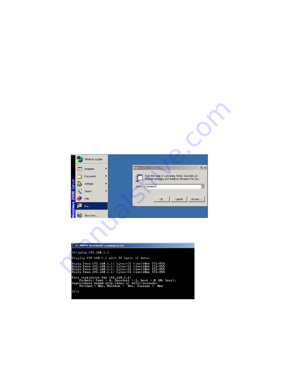
11. To enable the “Command Line mode”, click on
Run
in the Start menu, type
Command
, and
click on
OK
to continue.
12. Type ping
192.168.1.1
command to check the connection. Here we use IP address
192.168.1.1 as an example.
13. Repeat step 10 to make sure that the connection of each device connected to the JetNet is
successfully established.
14. Power on the host, activate the Command Line mode, and ping the connected Ethernet
device by typing “ping –t 192.168.1.1” command to see if it will respond.
15. The parameter ”t” allows you to continue to ping the network device, as shown in the figure
below.


