Korenix JetNet 3005 Скачать руководство пользователя страница 18


12. Power on the host, activate the Command Line mode, and ping the connected 

Ethernet device by typing “ping –t 192.168.1.1” command to see if it will 

respond. 


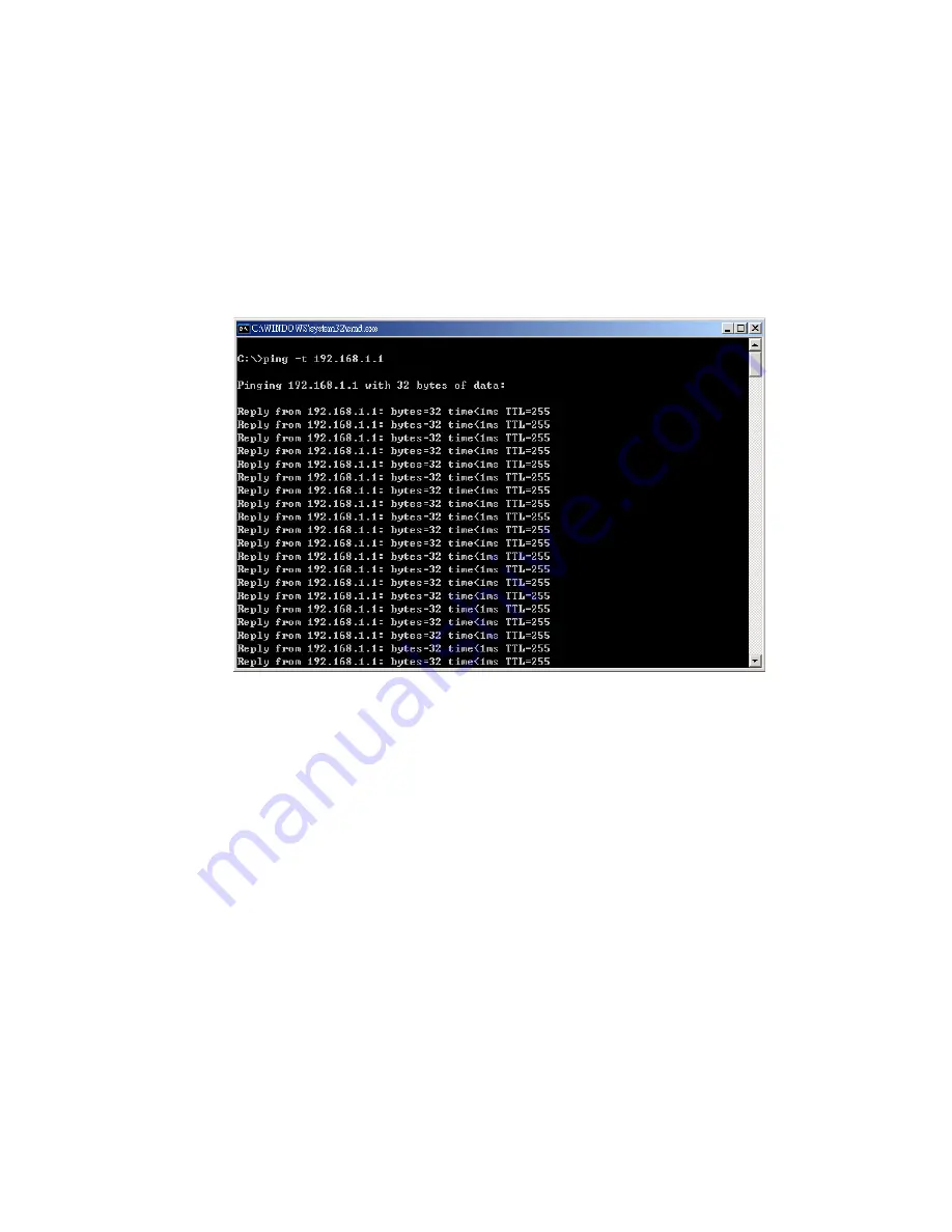
13. The parameter ”t” allows you to continue to ping the network device, as shown 

in the figure below. 


Before you continue, make sure that both PWR1 and PWR2 are successfully 

connected to power sources. When PWR1 fails, the LED for PWR1 will go out. At 

that moment, if the ping command is still being replied to, then it proves that the 

redundant power input function works normally. 


14. Exit the Command Line mode, and connect PWR1 power input. At this stage, 

your JetNet 3005/3008 has been tested and the installation is complete.   


15. To set up your industrial network by JetNet 3005 

15.1 See the figure below as an example. Computer A needs to connect 

several modems simultaneously in order to let a great number of users to access 

this industrial network. However, Computer A does not have additional COM ports 

to connect all of the modems. For this reason, we use a network solution. 

16


Содержание JetNet 3005

Страница 1: ...JetNet 3005 3008 Industrial Entry Level 5 port 8 port Ethernet Rail Switch User s Manual Rev 1 1 20 Jan 2005...

Страница 2: ...ckage Checklist 2 Hardware Description 3 Dimensions 3 Front Panel 3 Bottom View 5 Wiring the DC Power Inputs 5 LED Indicators 6 Ports 8 Cabling 9 DIN Rail Mounting 10 Wall Mounting 12 Hardware Install...

Страница 3: ...over an Ethernet network but also provides redundant power inputs and reverse polarity protection In addition JetNet 3005 3008 uses a IP30 aluminum case and has passed several safety certifications e...

Страница 4: ...hernet Rail Switch One DIN Rail clip attached with the JetNet 3005 3008 One wall mounting plate and six screws User s manual CD ROM Quick Installation Guide JetNet 3005 3008 Industrial Entry Level Use...

Страница 5: ...Rail Switch dimensions W x H x D are 54mm x 135mm x 105mm Front Panel The Front Panel of the JetNet 3005 Industrial Entry Level 5 port Ethernet Rail Switch is shown in Figure A LED Indicators UTP Por...

Страница 6: ...anel of the JetNet 3008 Industrial Entry Level 8 port Ethernet Rail Switch is shown in Figure A LED Indicators UTP Port Figure A Front Panel of the JetNet3008 Industrial Entry Level 8 port Ethernet Ra...

Страница 7: ...05 3008 Industrial Entry Level 5 port 8 port Ethernet Rail Switch Wiring the DC Power Inputs Follow the steps below to wire JetNet3005 3008 s dual DC power inputs Note The suitable electric wire range...

Страница 8: ...cription Green Power is on PWR Off No power is being supplied Green Power is on PWR 1 Off No power is being supplied Green Power is on PWR 2 Off No power is being supplied Green A network device is de...

Страница 9: ...f No device is attached Table 1 There are 7 diagnostic LEDs and 12 Port LEDs located on the Front panel of JetNet 3008 Industrial Ethernet Rail Switch These LED indicators provide administrators with...

Страница 10: ...ex mode or no device is attached Green A network device is detected Blinking green The port is transmitting or receiving packets from the TX device Port Status Port 1 to Port 6 Off No device is attach...

Страница 11: ...tches or hubs pin 1 2 3 and 6 of the 8 pin RJ45 connector are used to communicate with the connected devices Pin1 2 3 and 6 s signals are converted by the MDI X function as shown in Table 2 Pin MDI X...

Страница 12: ...ail clip is not screwed on the JetNet 3005 3008 follow the instructions and the figure below to attach the DIN Rail clip to the JetNet 3005 3008 Rear Panel of the JetNet 3005 3008 DIN Rail Clip 1 Use...

Страница 13: ...the upper end of the DIN Rail clip into the back of the DIN Rail track from its upper side 2 Lightly push the bottom of the DIN Rail clip into the track 3 Check if the DIN Rail clip is tightly attache...

Страница 14: ...en the screws from the DIN Rail clip 2 Place the wall mounting plate on the rear panel of the JetNet 3005 3008 3 Use the screws to tighten the wall mounting plate onto the JetNet 3005 3008 4 Use the h...

Страница 15: ...Level Rail Switch out of the package box 2 Check if the DIN Rail clip is attached to the JetNet 3005 3008 If the DIN Rail clip is not attached to the JetNet3005 refer to DIN Rail Mounting section for...

Страница 16: ...ormally Note If you are using DC IN power jack to supply power to the JetNet 3005 3008 please check the PWR LED 7 Use Category 5 straight through Ethernet cables with RJ45 connectors to connect networ...

Страница 17: ...the Command Line mode click on Run in the Start menu type Command and click on OK to continue 10 2 Type ping 192 168 1 1 command to check the connection Here we use IP address 192 168 1 1 as an exampl...

Страница 18: ...f the ping command is still being replied to then it proves that the redundant power input function works normally 14 Exit the Command Line mode and connect PWR1 power input At this stage your JetNet...

Страница 19: ...ice Manager and make sure the system each converter s IP address is mapped to the corresponding com port 15 6 Click on Computer A s Dialer and install modem driver Configure the modem s corresponding...

Страница 20: ...18...

Страница 21: ...4 5 Ethernet cables are suitable for systems with 10 Mbps transmission speed For systems with 100 Mbps transmission speed Category 5 Ethernet cables are the only suitable specifications for this envi...

Страница 22: ...t 148 800 pps for Fast Ethernet port MAC address table size JetNet3005 1K MAC address table JetNet3008 2K MAC address table Memory Buffer JetNet3005 512Kbits JetNet3008 1024Kbits LED Per port Link Act...

Страница 23: ...JetNet3008 1 19Mpps 64bytes 8TX Installation DIN Rail kit and wall mounting panel Operating Temperature 10 C to 70 C Operating Relative Humidity 5 to 95 non condensing Storage Temperature 40 C to 85 C...

Страница 24: ...IEC60068 2 6 Vibration 22...

Отзывы: