


KTD-00774-D
KTUS15/mITX
Page 8 of 82
www.kontron.com
!
Warning
: When mounting the board to chassis etc. please notice that the board contains
components on both sides of the PCB which can easily be damaged if board is handled
without reasonable care. A damaged component can result in malfunction or no function at all.
2 Installation
procedure
2.1
Installing the board
To get the board running, follow these steps. In some cases the board shipped from KONTRON Technology
has DDR2 DRAM mounted. In this case Step 2 can be skipped.
1. Turn off the PSU (power supply unit)
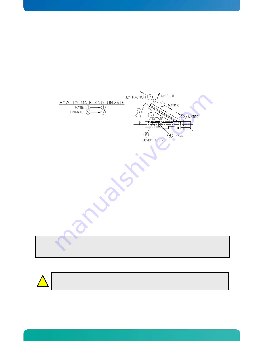
2. Insert the DDR2 SODIMM 200pin DRAM module
See guidelines below for assembling / disassembling memory module.
For a list of approved DDR2 DIMM modules contact your Distributor or FAE.
DDR2-400 and DDR2-533 SODIMM 200pin DRAM modules (PC3200, PC4200) are supported.
3. Connect
Interfaces
Insert all external cables for hard disk, keyboard etc. A CRT or DVI monitor (depending on actual
KTUS15 version) must be connected in order to change CMOS settings for flat panel support.
4. Connect the PSU and turn on the power to the PSU
Connect power supply to the board by the 6x2pin PWR connector.
Note
: the board is a single-supply board, accepting input voltages from 5V to 25V (DC). Power cables for
connecting the KTUS15 family boards to a ATX power supply (+5V or +12V) are available from Kontron
(P/N 1022-6309).
5. Power
Button
The PWRBTN_IN may be required to start the board; this is done by momentarily connecting together pins
16 (PWRBTN_IN) and pin 18 (GND) on the FRONTPNL connector (see Connector description), to provide
a pulse on the PWRBTN_IN pin. A “normally open” switch can be connected via the FRONTPNL
connector.
6. BIOS
Setup
Enter the BIOS setup by pressing the <Del> key during boot up. Refer to the “BIOS Configuration / Setup“
section of this manual for details on BIOS setup.
7. Mounting the board to chassis
When fixing the Motherboard on a chassis it is recommended using screws with integrated washer and
having diameter of ~7mm.
Note
: Do not use washers with teeth, as they can damage the PCB mounting hole and may cause short
circuits.
Note:
To clear all CMOS settings, including Password protection, move the Clr-CMOS jumper (with or
without power) for approximately 1 minute. This will also disable any Secure CMOS setup on the board.
Alternatively, turn off power and remove the battery for 1 minute, but be careful to orientate the battery
correctly when reinserted.


