COMe Ref. Carrier-i T6 TMI - User Guide Rev. 1.4
// 26
USB#6 is used for MiniPCIe half-size interface to enable usage of USB 2.0 high-speed Mini PCIe form factor
devices.
USB#7 is used for Mini PCIe full-size / mSATA interface to enable usage of USB 2.0 high- speed Mini PCIe form
factor devices.
2.3.6.
USB 3.0
The COMe Ref. Carrier-i T6 TMIP supports four super-speed USB 3.0 interfaces used as host:
USB_SS#[0;1] are routed to the USB 3.0/2.0 double-stack connector, J11.
USB_SS#[2;3]) are routed to the 20-pin USB 3.0/2.0 pin header, J7.
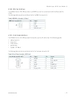
The following table provides pinout information for the USB 3.0/2.0 pin header, J7.
Table 8: USB 3.0/2.0 Pin Header J7 Pinout
USB 3.0/2.0 Pin Header (J7)
Pin
Signal
Pin
Signal
1
Power
20
2
SSRX2-
19
Power
3
SSRX2+
18
SSRX3-
4
GND
17
SSRX3+
5
SSTX2-
16
GND
6
SSTX2+
15
SSTX3-
7
GND
14
SSTX3+
8
USB2-
13
GND
9
USB2+
12
USB3-
10
NC
11
USB3+
2.3.7.
HD Audio Interfaces
The COMe Ref. Carrier-i T6 TMIP provides HD Audio via the industrial grade HD Audio Codec IDT / Tempo Semi
92HD73C (U13) through the following analog and digital audio connectors:
Rear panel line-in connector, J25
Rear panel SPK / line-out connector, J26
Front panel HD audio header, J22
S/PDIF header, J23
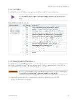
The following table provides pinout information for the front panel HD audio header, J22.
Table 9: Front Panel HD Audio Header J22 Pinout
Front Panel HD Audio Header (J22)
Pin
Signal
Pin
Signal
10
LINE2_JD
9
LINE2_L
8
7
SENSE
6
MIC2_JD
5
LINE2_R
4
PRESENCE#
3
MIC2_R
2
GNDA
1
MIC2_L


