background image

Installation

AM4011

Page 3 - 10

ID 1022-1626, Rev. 1.0

P R E L I M I N A R Y

3.4.3

USB 2.0 NAND Flash Module Installation

A USB 2.0 NAND Flash module may be connected to the AM4011 via the onboard USB 2.0
NAND Flash connector.

This optionally available module must be physically installed on the AM4011 prior to installation
of the AM4011 in a system. 

A spacer must be placed between the heat sink and the USB 2.0 NAND Flash module at the
fastening screw hole. This allows the module to be properly secured and prevents damage to
the module when the fastening screw is tightened. If the correct spacer is not available, contact
Kontron for further assistance.

During installation it is necessary to ensure that the USB 2.0 NAND Flash module is properly
seated in the onboard USB 2.0 NAND Flash connector, i.e. the pins are aligned correctly and
not bent.

Before putting the AM4011 into operation, ensure that the boot priority is configured as required
for the application.

3.5

Software Installation

The installation of the Ethernet and all other onboard peripheral drivers is described in detail in
the relevant Driver Kit files.

Installation of an operating system is a function of the OS software and is not addressed in this
manual. Refer to the appropriate OS software documentation for installation.  

Note ...

Users working with pre-configured operating system installation images for
Plug and Play compliant operating systems must take into consideration that
the stepping and revision ID of the chipset and/or other onboard PCI devices
may change. Thus, a re-configuration of the operating system installation im-
age deployed for a previous chipset stepping or revision ID is in most cases re-
quired. The corresponding operating system will detect new devices according
to the Plug and Play configuration rules.

Содержание AM4011

Страница 1: ...AM4011 User Guide P R E L I M I N A R Y Doc ID 1022 1626 Rev 1 0 May 6 2008 Single Mid and Full size AMC Module based on the Intel Core 2 Duo Processor with the Intel 3100 Chipset...

Страница 2: ...AG All rights reserved All data is for information purposes only and not guaranteed for legal purposes Information has been carefully checked and is believed to be accurate however no responsibility...

Страница 3: ...Handling and Unpacking Instructions xiii General Instructions on Usage xiv Two Year Warranty xv 1 Introduction 1 3 1 1 AdvancedTCA System Overview 1 3 1 2 Board Overview 1 4 1 2 1 Board Introduction 1...

Страница 4: ...face 2 10 2 3 5 Onboard USB 2 0 NAND Flash Connector 2 10 2 3 6 USB Host Interface 2 11 2 3 7 Serial Ports 2 12 2 3 8 Serial ATA Interface 2 14 2 3 9 Gigabit Ethernet Interfaces 2 14 2 4 AMC Interconn...

Страница 5: ...figuration 4 4 4 2 Interrupts 4 5 4 3 Memory Map 4 6 4 3 1 I O Address Map 4 6 4 4 AM4011 Specific Registers 4 6 4 4 1 BIOS Configuration Register 4 7 4 4 2 MMC I O Status Register 4 7 4 4 3 Watchdog...

Страница 6: ...odule Management Power Consumption 5 4 5 3 Payload Power Consumption of the AM4011 5 4 5 4 IPMI FRU Payload Power Consumption 5 5 5 5 Payload Start Up Current of the AM4011 5 6 6 Thermal Consideration...

Страница 7: ...Adapter Connectors 2 13 2 11 Gigabit Ethernet Con J3 and J4 Pinout Based on Implementation 2 15 2 12 Pinout of AMC Card edge Connector J1 2 19 2 13 Reserved Pins Description 2 22 2 14 Extended Options...

Страница 8: ...ter 4 13 4 19 User Specific LED Configuration Register 4 14 4 20 User Specific LED Control Register 4 15 4 21 Serial over LAN Configuration Register 4 16 4 22 Delay Timer Control Status Register 4 17...

Страница 9: ...ub Female Connector 2 13 2 8 Gigabit Ethernet Connectors J3 and J4 2 15 2 9 AM4011 Port Mapping 2 17 3 1 Module Handle Positions 3 4 3 2 Adapter for Mini USB Type A to USB Type A Connectors 3 8 3 3 Ad...

Страница 10: ...Preface AM4011 This page has been intentionally left blank Page x ID 1022 1626 Rev 1 0 P R E L I M I N A R Y...

Страница 11: ...of any circuit product or example shown in this document Kontron reserves the right to change modify or improve this document or the product described herein as seen fit by Kontron without further not...

Страница 12: ...Sensitive Device This symbol and title inform that electronic boards and their compo nents are sensitive to static electricity Therefore care must be taken during all handling operations and inspecti...

Страница 13: ...ischarged before touching the product with his her hands or tools This is most easily done by touching a metal part of your system housing Warning All operations on this device must be carried out by...

Страница 14: ...Technical Support as a special han dling instruction will void your warranty This device should only be installed in or connected to systems that fulfill all necessary techni cal and specific environ...

Страница 15: ...fund the original cost of purchase if appropriate In the event of repair refunding or replacement of any part the ownership of the removed or replaced parts reverts to Kontron and the remaining part o...

Страница 16: ...Preface AM4011 This page has been intentionally left blank Page xvi ID 1022 1626 Rev 1 0 P R E L I M I N A R Y...

Страница 17: ...AM4011 Introduction ID 1022 1626 Rev 1 0 Page 1 1 Introduction Chapter 1 1 P R E L I M I N A R Y...

Страница 18: ...Introduction AM4011 Page 1 2 ID 1022 1626 Rev 1 0 P R E L I M I N A R Y This page has been intentionally left blank...

Страница 19: ...l support high power capability hot swappability high scalability and integrated system management For further information regarding the AdvancedTCA MicroTCA standards and their use please consult the...

Страница 20: ...manage the board and support a defined subset of Intelligent Platform Management Interface IPMI commands and PICMG ATCA AMC command extensions which enables operators to detect and eliminate faults fa...

Страница 21: ...he Extended Options Region PCI Express clock reference input FCLKA Full hot swap support Two Intel 82571EB Dual Gigabit Ethernet controllers One controller connected to the Common Options Region One c...

Страница 22: ...rt mapping Common Options Region ports 0 1 Two Gigabit Ethernet SerDes ports Common Options Region ports 2 3 Two Serial ATA 150 ports Fat Pipes Region ports 4 7 One x4 PCI Express interface Extended O...

Страница 23: ...Reg Serial Intel Core 2 Duo 1 5 GHz 667 MHz ITP Debug Temp Sense EEP 64 kbit I 2 C Intel 3100 chipset COM USB DDR2 PCIe B PCIe A LPC FSB SATA 2 3 Intel Dual GbE 82571EB SERDES SERDES x4 PCIe x4 PCIe...

Страница 24: ...n the hot swap state of the module The HS LED states are off short blink long blink and on User Specific LEDs ULED3 red green AMC Eth port A link signal status or BIOS POST code LED ULED2 red green Fr...

Страница 25: ...d Layouts Figure 1 3 AM4011 Board Layout Top View Figure 1 4 AM4011 Board Layout Bottom View Intel Core 2 Duo 1 5 GHz Intel 3100 Chipset J8 1 J1 1 85 GbE Contr GbE Contr USB 2 0 NAND Flash J4 J3 J2 J5...

Страница 26: ...Bus interface at up to 667 MHz System Memory interface with optimized support for DDR2 SDRAM memory at 400 MHz with ECC Three x4 PCI Express ports RASUM Reliability Availability Serviceability Usabili...

Страница 27: ...pin mini USB type A connector One Serial port COM1 with RS 232 signal level on a mini 10 pin con nector Two Gigabit Ethernet ports on two RJ 45 connectors Onboard Connector One USB 2 0 connector for o...

Страница 28: ...a a local IPMB IPMB L and two host Key board Style Interfaces KCS Hot Swap The AM4011 has full hot swap capability Thermal Management CPU and board overtemperature protection is provided by Four tempe...

Страница 29: ...oot from USB device floppy CD ROM hard disk memory stick BIOS support for USB keyboards Plug and Play capability BIOS parameters are saved in the EEPROM Board serial number is saved within the EEPROM...

Страница 30: ...nd Health Aspects Vibration sinusoidal IEC60068 2 6 5 150 Hz 1 g 1 oct min 10 cycles axis 3 directions x y z Vibration sinusoidal transportation IEC60068 2 6 2 50 Hz 1 g 0 1 oct min 50 500 Hz 3 g 0 25...

Страница 31: ...Computing Architecture R1 0 July 6 2006 AMC PICMG AMC 0 Advanced Mezzanine Card Specification R2 0 PICMG AMC 1 PCI Express and Advanced Switching R1 0 PICMG AMC 2 Gigabit Ethernet R1 0 PICMG AMC 3 Sto...

Страница 32: ...Introduction AM4011 Page 1 16 ID 1022 1626 Rev 1 0 P R E L I M I N A R Y This page has been intentionally left blank...

Страница 33: ...AM4011 Functional Description ID 1022 1626 Rev 1 0 Page 2 1 Functional Description Chapter 1 2 P R E L I M I N A R Y...

Страница 34: ...Functional Description AM4011 Page 2 2 ID 1022 1626 Rev 1 0 P R E L I M I N A R Y This page has been intentionally left blank...

Страница 35: ...thout resetting the system The frequency for the processor may also be selected in the BIOS or via the operating system The following list sets out some of the key features of the Intel Core 2 Duo pro...

Страница 36: ...re available on the AM4011 board 2 2 1 Timer The AM4011 is equipped with the following timers Real Time Clock The Intel 3100 chipset integrates a MC146818A compatible real time clock with 256 Byte CMO...

Страница 37: ...the MMC controller or the DIP switch If one Firmware Hub Flash is corrupted the MMC can enable the second Firmware Hub Flash and boot the system again The Firmware Hub Flash includes a hardware write...

Страница 38: ...Service LED red Off Default By user Only lamp test On MMC out of service or in reset state Slow Blinking MMC upgrade Fast Blinking Traffic on IPMB L LED2 Health LED red On Blinking Health error detect...

Страница 39: ...Ethernet port A link signal status ULED2 red When lit up during boot up it indicates a clock failure processor overtemperature above 125 C blinking and chipset overtemperature above 105 C on green BIO...

Страница 40: ...OST Code Example LED3 LED2 LED1 LED0 RESULT HIGH NIBBLE off 0 on 1 off 0 off 0 0x4 LOW NIBBLE off 0 off 0 off 0 on 1 0x1 POST CODE 0x41 Note Under normal operating conditions the User Specific LEDs sh...

Страница 41: ...in the Locked position and the following actions result The module is locked in the carrier chassis The hot swap switch is actuated Hot Swap When an extraction process of the AM4011 is initiated the...

Страница 42: ...ng hardware failures and BIOS POST code An optional ITP700 processor JTAG connector J9 is included to facilitate debug and BIOS software development 2 3 5 Onboard USB 2 0 NAND Flash Connector The AM40...

Страница 43: ...figure illustrates the adapter required for connecting standard USB devices to the AM4011 For further technical or ordering information on this adapter please contact Kontron s Technical Support Figur...

Страница 44: ...ce includes only receive and transmit signals Data transfer rates up to 115 2 kB s are supported COM2 is available on the AMC port 15 in the Extended Options Region of the AMC Card edge Connector as T...

Страница 45: ...f the Serial Adapter Connectors PINOUT OF THE D SUB CONNECTOR SIGNAL PINOUT OF THE MINI CONNECTOR 1 Not used 1 3 RX 2 2 TX 3 4 Not used 4 5 GND 5 6 Not used 6 7 Not used 7 8 Not used 8 9 Not used 9 No...

Страница 46: ...orts are rout ed to the AMC ports 0 1 in the Common Options Region of the AMC Card edge Connector The Intel 82571EB Dual Gigabit Ethernet controller is optimized to deliver high performance data throu...

Страница 47: ...MDIX CROSSED ETHERNET CABLE 10BASE T 100BASE TX 1000BASE T 10BASE T 100BASE TX 1000BASE T I O SIGNAL I O SIGNAL I O SIGNAL I O SIGNAL I O SIGNAL I O SIGNAL O TX O TX I O BI_DA 1 I RX I RX I O BI_DB O...

Страница 48: ...e detailed information on these interfaces 2 4 1 Fabric Interface The Fabric interface is the real communication path and comprises 20 high speed ports pro viding point to point connectivity for modul...

Страница 49: ...rt Mapping Clocks Common Options Region TCLKA TCLKB FCLKA 0 1 2 3 4 5 6 7 8 9 10 11 Fat Pipes Region 12 13 14 15 17 18 19 20 Extended Options Region GbE A GbE B SATA A SATA B x4 PCI Express AM4011 Por...

Страница 50: ...e Local Intelli gent Platform Management Bus IPMB L The Module Management Controller uses this port for the communication with the carrier Intelligent Platform Management Controller IPMC The IPMB L is...

Страница 51: ...164 GND Logic Ground 8 RSV Reserved 163 Tx20 Not Connected AMC 9 PWR Payload Power Carrier 162 Tx20 Not Connected AMC 10 GND Logic Ground 161 GND Logic Ground 11 Tx0 GbE A Transmitter AMC 160 Rx20 Not...

Страница 52: ...nd 128 GND Logic Ground 44 Tx4 PCIe 0 Transmitter AMC 127 Tx14 Debug serial data output AMC 45 Tx4 PCIe 0 Transmitter AMC 126 Tx14 Debug serial clock output AMC 46 GND Logic Ground 125 GND Logic Groun...

Страница 53: ...com Clock A optional Carrier 97 Tx9 Not Connected AMC 75 TCLKA Telecom Clock A optional Carrier 96 Tx9 Not Connected AMC 76 GND Logic Ground 95 GND Logic Ground 77 TCLKB Not Connected AMC 94 Rx9 Not C...

Страница 54: ...tion Table 2 14 Extended Options Region Pins Description AMC PIN AMC PORT FUNCTION I O SIGNALING VOLTAGE 133 15 Tx serial port COM2 O 3 3V TTL level 132 15 Rx serial port COM2 I 3 3V TTL level 127 14...

Страница 55: ...anages hot swap LEDs and op erations reboots the board etc Additionally the MMC can intervene in the operating status of the system by reading temperature values shutting down systems generating alarm...

Страница 56: ...C Specific Signals SIGNAL DESCRIPTION MMC FUNCTION GA 0 2 Geographic address Monitor and control Hot swap LED Hot swap LED Control LED Hot swap switch Status of hot swap switch Monitor switch User Spe...

Страница 57: ...e connector Monitor temperature Outlet AMC sensor temperature Outlet board temperature sensor near the AMC Card edge connector Monitor temperature Inlet processor temperature Inlet board temperature s...

Страница 58: ...Functional Description AM4011 Page 2 26 ID 1022 1626 Rev 1 0 P R E L I M I N A R Y This page has been intentionally left blank...

Страница 59: ...AM4011 Installation ID 1022 1626 Rev 1 0 Page 3 1 Installation Chapter 1 3 P R E L I M I N A R Y...

Страница 60: ...Installation AM4011 This page has been intentionally left blank Page 3 2 ID 1022 1626 Rev 1 0 P R E L I M I N A R Y...

Страница 61: ...son when inserting or extracting the module apply only as much force as required to preclude damage to either the module s handle or the front panel DO NOT push on the module handle to seat the module...

Страница 62: ...v 1 0 P R E L I M I N A R Y 3 2 Module Handle Positions The module handle supports a three position operation Figure 3 1 Module Handle Positions Note For normal operation the module handle must be in...

Страница 63: ...the carrier backplane connector 5 Apply pressure to the front panel until the module is properly seated in the carrier back plane connector This may require a considerable amount of force Apply pressu...

Страница 64: ...record and the AMC Point to Point Connectivity record If the module FRU information is valid and the carrier can provide the necessary pay load power the BLUE HS LED will be turned off The carrier now...

Страница 65: ...ermission from the higher level management Shelf Man ager or System Manager to proceed with its deactivation Once the module receives the permission to continue the deactivation all used ports are dis...

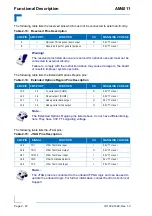
Страница 66: ...tion aspects and not detailed procedures 3 4 1 Installation of USB Devices The AM4011 supports the installation of standard USB peripheral devices via an adapter for Mini USB type A to USB type A conn...

Страница 67: ...gned adapter for a 10 pin mini connector to a 9 pin female D Sub connector from Kontron Figure 3 3 Adapter for 10 Pin Mini Connector to 9 Pin D Sub Female Connector For further technical or ordering i...

Страница 68: ...e the pins are aligned correctly and not bent Before putting the AM4011 into operation ensure that the boot priority is configured as required for the application 3 5 Software Installation The install...

Страница 69: ...AM4011 Configuration ID 1022 1626 Rev 1 0 Page 4 1 Configuration Chapter 1 4 P R E L I M I N A R Y...

Страница 70: ...Configuration AM4011 This page has been intentionally left blank Page 4 2 ID 1022 1626 Rev 1 0 P R E L I M I N A R Y...

Страница 71: ...h 2 for BIOS Firmware Hub Flash configuration switch 3 for boot order configuration and switch 4 for clearing the BIOS CMOS parameters Figure 4 1 DIP Switch The following table indicates the functions...

Страница 72: ...setting is indicated by using italic bold 4 1 3 Boot Order Configuration Switch 3 enables the user to set the BIOS boot order For further information on the boot order configuration refer to section...

Страница 73: ...a the BIOS settings Table 4 6 Interrupt Setting IRQ PRIORITY STANDARD FUNCTION IRQ0 1 System Timer IRQ1 2 Free Keyboard Controller IRQ2 Input of the second IRQ controller IRQ8 IRQ15 IRQ3 11 COM2 IRQ4...

Страница 74: ...ST Code 0x84 Debug POST Code 0x280 BIOS Configuration Register 0x281 MMC I O Status Register 0x282 Watchdog Timer Control Register 0x283 AMC Geographic Addressing Register 0x284 Board and Logic Revisi...

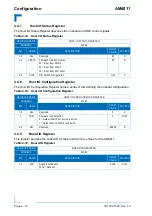
Страница 75: ...S configuration 00 R 2 0 BBOCON BIOS boot order configuration 000 Default BIOS boot order configuration If the DIP switch 3 is on the default BIOS boot order configuration is selected 0 R Table 4 9 MM...

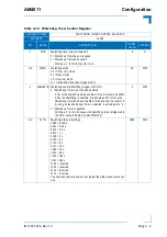
Страница 76: ...og is enabled using the required timeout period Normally the Watchdog is retriggered by writing a 1 to the WTR bit In the event a timeout occurs the WTE bit is set to 1 This bit can then be polled by...

Страница 77: ...rol bit 0 Watchdog Timer has not been enabled Prior to the Watchdog being enabled this bit is known as WEN After the Watchdog is enabled it is known as WTR Once the Watchdog Timer has been enabled thi...

Страница 78: ...andling by the software It starts with the value 0x00 for the initial board prototypes and will be incremented with each change in hardware or logic as development continues Table 4 11 AMC Geographic...

Страница 79: ...n 0 System reset generated by software warm reset 1 System reset generated by power on cold reset Writing a 1 to this bit clears this bit N A R W 6 4 Res Reserved N A R 3 MRST MMC reset the host proce...

Страница 80: ...REGISTER ADDRESS 0x286 BIT NAME DESCRIPTION RESET VALUE ACCESS 7 6 Res Reserved 00 R 5 4 FBSTA Firmware Hub boot status 00 Boot from FWH0 01 Boot from FWH1 10 Boot from LPC FWH 00 R 3 0 DIPS DIP Swit...

Страница 81: ...handle status Table 4 17 Board Interrupt Configuration Register REGISTER NAME BOARD INTERRUPT CONFIGURATION REGISTER ADDRESS 0x289 BIT NAME DESCRIPTION RESET VALUE ACCESS 7 2 Res Reserved 000000 R 1...

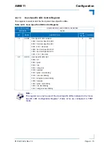
Страница 82: ...POST bit 1 and bit 5 green ULED2 POST bit 2 and bit 6 green ULED3 POST bit 3 and bit 7 green For further information on reading the 8 Bit BIOS POST Code refer to section 2 3 1 Front Panel LEDs 2 Confi...

Страница 83: ...et User Specific LED 0 0001 Get User Specific LED 1 0010 0111 Reserved 1000 Set User Specific LED 0 1001 Set User Specific LED 1 1010 1111 Reserved 0 R W 3 0 ULCOL User Specific LED color 0000 off 000...

Страница 84: ...y the MMC Table 4 21 Serial over LAN Configuration Register REGISTER NAME SERIAL OVER LAN CONFIGURATION REGISTER ADDRESS 0x28E BIT NAME DESCRIPTION RESET VALUE ACCESS 7 4 SCOM Host COM1 port configura...

Страница 85: ...bility Therefore writing a 0 to the Delay Timer Control Status Register followed by reading indicates the timer capability not the timer outputs For example writing 0x00 and then reading 0xFF results...

Страница 86: ...rrupt Table 4 23 MMC Configuration Register REGISTER NAME MMC CONFIGURATION REGISTER ADDRESS 0x29C BIT NAME DESCRIPTION RESET VALUE ACCESS 7 MPGC MMC program request 0 No action 1 Request MMC to progr...

Страница 87: ...AM4011 Power Considerations ID 1022 1626 Rev 1 0 Page 5 1 Power Considerations Chapter 1 5 P R E L I M I N A R Y...

Страница 88: ...Power Considerations AM4011 This page has been intentionally left blank Page 5 2 ID 1022 1626 Rev 1 0 P R E L I M I N A R Y...
Страница 89: ...should be selected at the higher end of the specified voltage range The continuous current limit value is based on the power limit of 60 W per module at the minimum supply value The maximum current v...

Страница 90: ...alculate the payload power consumption for the AM4011 board with different configurations and applications The processor the chipset and the memory dissipate the majority of the payload power The payl...

Страница 91: ...ocessor corresponds to the maximum Thermal Design Power TDP as specified in the respective datasheet for the Intel Core 2 Duo processor Linux Intel Thermal Analysis Tool TAT at 100 no real application...

Страница 92: ...of the AM4011 during the first 2 3 sec onds after the payload power has been applied The payload power consumption of the AM4011 during operation is indicated in Table 5 2 For further information on t...

Страница 93: ...AM4011 Thermal Considerations ID 1022 1626 Rev 1 0 Page 6 1 Thermal Considerations Chapter 1 6 P R E L I M I N A R Y...

Страница 94: ...Thermal Considerations AM4011 This page has been intentionally left blank Page 6 2 ID 1022 1626 Rev 1 0 P R E L I M I N A R Y...

Страница 95: ...onality at the max imum temperature the BIOS and the Module Management Controller support several temperature monitoring and control features The AM4011 includes six temperature sensors that are acces...

Страница 96: ...1 Placement of the Temperature Sensors Figure 6 1 Board Temperature Sensor Placement AM4011 Bottom View Figure 6 2 Processor Temperature Sensor Placement AM4011 Top View Inlet AMC Sensor Outlet AMC S...

Страница 97: ...Thermal Monitor 2 TM2 Sensor and the Cata strophic Cooling Failure Sensor are not accessible They serve for protecting the processor from overheating These sensors are integrated in the processor and...

Страница 98: ...d reports the event via an external signal to the Module Management Controller In this case the processor reduces its operating frequency and processor core voltage This combination of reduced fre que...

Страница 99: ...e The Intel 3100 chipset includes one on die Thermal Diode Sensor used by the Module Man agement Controller to measure the chipset die temperature The maximum Intel 3100 chipset case temperature is 10...

Страница 100: ...upport forced airflow concepts as found in modern AMC carriers and MicroTCA systems 6 2 1 Forced Airflow in MicroTCA Systems When developing applications using the AM4011 the system integrator must be...

Страница 101: ...22 1626 Rev 1 0 Page 6 9 P R E L I M I N A R Y Figure 6 4 Temperature vs Airspeed Graph of a Full Size AM4011 Note The maximum airflow input temperature was measured at the bottom of the board just be...

Страница 102: ...e depends on individual configuration of the AMC carrier or MicroTCA system The following figure shows the impedance curves of a Mid size and a Full size AM4011 module Figure 6 5 Mid Size and Full Siz...

Страница 103: ...lowing table indicates the deviation of the airflow rate on a Mid size AM4011 module Table 6 2 Deviation of the Airflow Rate on a Mid Size AM4011 VOLUMETRIC FLOW RATE CFM DEVIATION OF THE AIRFLOW RATE...

Страница 104: ...THE AIRFLOW RATE ZONE B ZONE D ZONE C ZONE D 10 4 0 2 86 2 86 1 71 20 4 0 2 29 2 86 1 14 30 3 82 2 29 2 64 1 15 40 3 87 1 87 2 44 0 43 Note The Full size AM4011 module has an airflow rate deviation of...

Отзывы: