


AT8901M
Hardware Description
Page 3 - 7
AT8901M User Guide
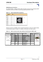
Base Interface Uplink
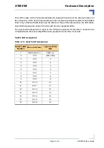
The Hub Board supports four base interface uplinks to the front panel. The switch is connected
to the RJ45 connectors with integrated status LEDs on the front panel via a 10/100/1000BASE-
T quad PHY and two 10/100/1000BASE-T dual magnetics. GbE channels 0/1 to 0/4 of the
switch map to uplink channels 1 to 4.
Table 3-8: Base Uplink (J39/J38) LEDs Signification
Table 3-7: Base Uplink (J39/J38) Pin Assignment
Signal
Pin
DB+
1
DB-
2
DA+
3
DD+
4
DD-
5
DA-
6
DC+
7
DC-
8
Speed LED (yellow)
OFF
10BASE-T
BLINK
100BASE-TX
ON
1000BASE-T
Status LED (green)
OFF
Link Down
ON
Link Up and no activity
BLINK
Link Up and activity
Yellow
Green
Yellow
Green
1
8
1
1
8
Содержание AdvancedTCA AT8901M
Страница 1: ...AT8901M USER GUIDE AdvancedTCA 3 5 Revision Index February 2009 Date of Issue...
Страница 14: ...AT8901M Introduction Page 1 1 AT8901M User Guide Introduction Chapter 1...
Страница 25: ...Installation Chapter 2 Page 2 1 AT8901M User Guide AT8901M Installation...
Страница 31: ...Hardware Description Chapter 3 Page 3 1 AT8901M User Guide AT8901M Hardware Description...
Страница 51: ...Software Description Page 4 1 AT8901M User Guide AT8901M Software Description Chapter 4...
Страница 72: ...AT8901M Getting Help Page A 1 AT8901M User Guide Getting Help Appendix A...


