background image


page 7 

KP Strong Safe, grade II 


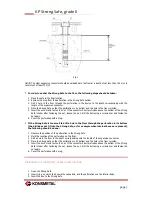
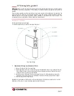
Fig. 1 


NOTE:

 The steel expansion connector should be embedded in the floor at a depth of not less than 130 mm, in 

concrete of at least C12/15 


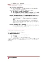
In order to anchor the Strong Safe to the floor, the following steps should be taken: 


1.


Place the safe in the final location. 

2.


Remove the plug from the perforation in the Strong Safe bottom. 

3.


Drill  a  hole  in  the  floor  through  the  perforation  in  the  device  to  the  depth  corresponding  with  the 
length of the expansion connector.  

4.


Place the Strong Safe so that the perforation in its bottom and the hole in the floor coincide.  

5.


Insert the anchor and fasten the nut. If the connector’s bolt protrudes above the bottom of the Strong 

Safe interior after fastening the nut, loosen the nut, drill the bolt using a screwdriver and fasten the 
nut again. 

6.


Cover the perforation with a plug. 


If the Strong Safe is too small to drill a hole in the floor through the perforation in its bottom 
(the drill does not fit into the Strong Safe, or for example when internal boxes are present), 

the following should be done: 


1.


Measure the position of the perforation in the Strong Safe 

2.


Mark the location of the perforation on the floor. 

3.


Drill a hole in the floor to the depth corresponding with the length of the expansion connector. 

4.


Place the Strong Safe so that the perforation in its bottom and the hole in the floor coincide.  

5.


Insert the anchor and fasten the nut. If the connector’s bolt protrudes above the bottom of the Strong 

Safe interior after fastening the nut, loosen the nut, drill the bolt using a screwdriver and fasten the 
nut again. 

6.


Cover the perforation with a plug. 


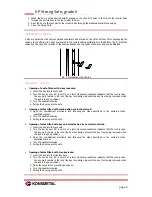
Installation of separately lockable internal box 


1.


Open the Strong Safe. 

2.


Insert clips, on which the box will be supported, into the perforations on the interior body. 

3.


Insert the box to the Strong Safe 

Содержание Grade II

Страница 1: ...Product card User manual KP Strong Safe Grade II KONSMETAL Export Department export konsmetal pl KONSMETAL Service phone 48 89 6253799 Monday Friday 8 16 e mail serwis konsmetal pl...

Страница 2: ...Types of locks 5 Standard colors 5 Specifications 5 Installation of separately lockable internal box 7 Installation of shelves 8 Operation opening 8 Operation closing 9 Operation separately lockable i...

Страница 3: ...default code on its own unknown to third parties BEFORE using the device Leaving default code is a threat to the security of deposited values Changing the code and test of the new code in the combina...

Страница 4: ...lock with two keys Shelves with a suspension height adjustment maximum shelf load 50kg Clips for shelf mounting Perforations in the Strong Safe s bottom 28 mm Operating manual for the installed combin...

Страница 5: ...KP Strong Safe grade II Types of locks key combination electronic Standard colors Light grey RAL 7035 Light grey RAL 9002 Black RAL 9005 Any color from the RAL palette to order powder coated Specific...

Страница 6: ...rnal box Rotary handle H KP 67 1 YES 32 80 KP 100 2 YES 40 125 KP 120 3 YES 40 125 KP 150 4 YES 40 125 Can be mounted as additional equipment Separately lockable internal box External dimensions mm Do...

Страница 7: ...ver the perforation with a plug If the Strong Safe is too small to drill a hole in the floor through the perforation in its bottom the drill does not fit into the Strong Safe or for example when inter...

Страница 8: ...Turn the handle clockwise 4 Pulling the door opens the safe Opening of safes fitted with combination or electronic lock 1 Open the combination electronic lock following the steps described in the enc...

Страница 9: ...the key to the lock and turn it to the right by more than 90 above 1 4 of a rotation 2 Box is opened after pulling the door outwards Box closing 1 Push the door against the box body 2 Rotate the key...

Страница 10: ...battery is located in an external lock keyboard a Open the safe b Remove the black cover of the battery compartment located on the inside of the safe door c Replace the battery noting the polarity the...

Страница 11: ...t of hinges KP Strong Safes have external hinges To make an adjustment you need two hex keys of size 4mm Fig 3 Upper hinge Adjustment of hinges is performed as follows 1 Remove the plug 4 from the upp...

Страница 12: ...ituation signaling by the relevant model of the lock can be found in the lock manual WARNING Triple attempt of entering the wrong code moves the lock into punishment mode which means that the lock wil...

Отзывы: