background image

C-1

Composition of the service manual

This service manual consists of Theory of Operation section and Field Service section to

explain the main machine and its corresponding options.

Theory of Operation section gives, as information for the CE to get a full understanding of

the product, a rough outline of the object and role of each function, the relationship

between the electrical system and the mechanical system, and the timing of operation of

each part.

Field Service section gives, as information required by the CE at the site (or at the cus-

tomer’s premise), a rough outline of the service schedule and its details, maintenance

steps, the object and role of each adjustment, error codes and supplementary information.

The basic configuration of each section is as follows. However some options may not be

applied to the following configuration.

<Theory of Operation section>

<Field Service section>

OUTLINE:

Explanation of system configuration, 

product specifications, unit configuration, and paper path

COMPOSITION/OPERATION: Explanation of configuration of each unit, 

operating system, and control system

GENERAL:

Explanation of system configuration, and product 

specifications

MAINTENANCE:

Explanation of service schedule, maintenance steps, ser-

vice tools, removal/reinstallation methods of major parts,

and firmware version up method etc.

ADJUSTMENT/SETTING:

Explanation of utility mode, service mode, and mechanical

adjustment etc.

TROUBLESHOOTING:

Explanation of lists of jam codes and error codes, and

their countermeasures etc.

APPENDIX:

Parts layout drawings, connector layout drawings, timing

chart, overall layout drawing are attached.

Содержание Magicolor 5650EN

Страница 1: ...SERVICE MANUAL 2008 04 2008 04 Ver 1 0 Ver 1 0 FIELD SERVICE magicolor 5650EN 5670EN ...

Страница 2: ...TAKE IN CASE OF AN ACCIDENT S 21 Composition of the service manual C 1 Notation of the service manual C 2 magicolor 5650EN 5670EN Main body General 1 Maintenance 7 Adjustment Setting 97 Troubleshooting 199 Appendix 243 Lower feeder unit General 1 Maintenance 3 Adjustment Setting 13 Troubleshooting 15 Duplex option General 1 Maintenance 3 Troubleshooting 9 Staple finisher General 1 Maintenance 5 Tr...

Страница 3: ...rmation The basic configuration of each section is as follows However some options may not be applied to the following configuration Theory of Operation section Field service section OUTLINE Explanation of system configuration product specifications unit configuration and paper path COMPOSITION OPERATION Explanation of configuration of each unit operating system and control system GENERAL Explanat...

Страница 4: ...SERVICE MANUAL 2008 04 Ver 1 0 FIELD SERVICE Main body magicolor 5650EN 5670EN ...

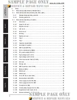
Страница 5: ... roller 12 3 4 2 Replacing the tray 1 feed roller 13 3 4 3 Replacing the ozone filter 16 3 4 4 Replacing the toner cartridge C M Y K 16 3 4 5 Replacing the imaging unit C M Y K 19 3 4 6 Replacing the waste toner bottle 23 3 4 7 Replacing the transfer roller 24 3 4 8 Replacing the transfer belt 25 3 4 9 Replacing the fuser unit 27 4 Service tool 28 4 1 CE tool list 28 4 2 Consumable parts 28 4 2 1 ...

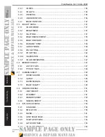
Страница 6: ... 2 53 6 3 9 Tray 1 54 6 3 10 Operation board OB 54 6 3 11 Hard disk kit option 55 6 3 12 MFP board MFPB 56 6 3 13 Print control board PRCB 59 6 3 14 DC power supply DCPU 61 6 3 15 High voltage unit 1 HV1 63 6 3 16 High voltage unit 2 HV2 64 6 3 17 Toner level sensor board TLSB 65 6 3 18 PH Unit 68 6 3 19 Driving unit 75 6 3 20 MFP board fan motor FM5 76 6 3 21 Backup battery 77 6 3 22 PWB box 1 78...

Страница 7: ...ent section 97 8 Description of the control panel 98 8 1 Control panel display 98 8 1 1 Parts of the control panel display 98 8 1 2 Message structure 99 8 1 3 Normal messages 100 8 1 4 Operator call messages 105 8 1 5 Service call messages 106 8 1 6 Help screen 107 8 2 List of control panel messages 108 8 2 1 Normal messages 108 8 2 2 Operator call messages 111 8 2 3 Service call messages 114 8 3 ...

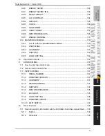
Страница 8: ...139 9 5 8 PCL SETTING 140 9 5 9 PS SETTING 142 9 5 10 CALIBRATION 146 9 5 11 COLOR SEPARATION 147 9 6 MEMORY DIRECT 147 9 6 1 LIST OF FILES 147 9 6 2 TYPE OF FILES 148 9 7 CAMERA DIRECT 148 9 7 1 PAPER SOURCE 148 9 7 2 LAYOUT 148 9 7 3 PAPER MARGIN 148 9 7 4 IMAGE QUALITY 149 9 8 INTERFACE MENU 151 9 8 1 JOB TIMEOUT 151 9 8 2 ETHERNET 151 9 8 3 MEMORY DIRECT 158 9 8 4 CAMERA DIRECT 158 9 9 SYS DEF...

Страница 9: ...MENU 178 9 10 3 ALIGNMENT 179 9 10 4 SUPPLIES 182 9 10 5 QUICK SETTING 182 10 Adjustment item list 184 11 SERVICE MENU 185 11 1 How to enter the service menu 185 11 2 Service menu function tree 186 11 3 SERVICE MENU 187 11 3 1 SERIAL NUMBER 187 11 3 2 FIRMWARE VERSION 187 11 3 3 ALIGNMENT 187 11 3 4 DIAGNOSIS MENU 191 11 3 5 SUPPLIES 194 11 3 6 RESTORE PASSWARD 195 11 3 7 BK CLEAR 195 11 3 8 QUICK...

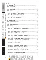
Страница 10: ...n 211 14 3 4 001B Developing motor Y M C malfunction 211 14 3 5 0046 Fusing fan motor malfunction 212 14 3 6 004C Ozone ventilation fan motor malfunction 212 14 3 7 004E DC power supply fan motor malfunction 213 14 3 8 0060 Fusing motor malfunction 213 14 3 9 0094 2nd image transfer pressure retraction failure 214 14 3 10 0096 1st image transfer pressure retraction failure 215 14 3 11 0300 Polygon...

Страница 11: ... C051 HDD full error 220 14 3 37 C052 Compact flash access error 220 14 3 38 C053 Compact flash full error 221 14 3 39 C060 Firmware update error 221 14 3 40 C071 Hardware configuration error 222 14 3 41 FFFF Interface communication error 222 15 Power supply troubles 223 15 1 Machine is not energized at all DCPU operation check 223 15 2 Control panel indicators do not light 223 15 3 Fusing heaters...

Страница 12: ...r fusing performance offset 238 16 1 15 Brush effect 239 16 1 16 Back marking 240 16 1 17 Uneven pitch 241 16 1 18 No print cycles can be run as commanded via the network 242 Appendix 17 Parts layout drawing 243 17 1 Main body 243 17 2 Lower feeder unit option 246 17 3 Duplex option option 247 17 4 Staple finisher option 248 18 Connector layout drawing 251 19 Timing chart 252 ...

Страница 13: ...n 1 magicolor 5650EN 5670EN General 1 System configuration System front view 1 magicolor 5650EN magicolor 5670EN magicolor 5670EN MPC type 4 Lower feeder unit 2 Duplex option 5 Lower feeder unit 3 Hard disk kit 6 Staple finisher A011F1C501DA 4 5 6 2 1 3 ...

Страница 14: ...SERVICE MANUAL 2008 04 2008 04 Ver 1 0 Ver 1 0 magicolor 5650EN 5670EN THEORY OF OPERATION ...

Страница 15: ...ii Blank Page ...

Страница 16: ...erformance and safety Such modifications are therefore strictly prohibited the points listed below are not exhaustive but they illustrate the reason ng behind this policy SAFETY WARNINGS Prohibited Actions DANGER Using any cables or power cord not specified by KMBT Using any fuse or thermostat not specified by KMBT Safety will not be assured leading to a risk of fire and injury Disabling fuse func...

Страница 17: ...e This area generates high voltage Be careful not to touch here when the power is turned ON to avoid getting an elec tric shock High voltage This area generates high voltage Be careful not to touch here when the power is turned ON to avoid getting an elec tric shock ...

Страница 18: ...of a serious accident has been received from a customer an on site evalua tion must be carried out quickly and KMBT must be notified 3 To determine the cause of the accident conditions and materials must be recorded through direct on site checks in accordance with instructions issued by KMBT 4 For reports and measures concerning serious accidents follow the regulations speci fied by every distribu...

Страница 19: ...formation The basic configuration of each section is as follows However some options may not be applied to the following configuration Theory of Operation section Field Service section OUTLINE Explanation of system configuration product specifications unit configuration and paper path COMPOSITION OPERATION Explanation of configuration of each unit operating system and control system GENERAL Explan...

Страница 20: ...magicolor 5650EN 5670EN Outline Composition Operation Theory of operation Ver 1 0 Apr 2008 vi Blank Page ...

Страница 21: ...size Minimum size 92 mm x 148 mm 3 6 inch x 5 8 inch Maximum size 216 mm x 297 mm 8 5 inch x 11 69 inch Media types Tray 1 Manual tray Plain paper 60 to 90 g m2 16 to 24 lb Recycled paper 60 to 90 g m2 16 to 24 lb Thick stock 1 91 to 150 g m2 24 to 40 lb Thick stock 2 128 to 210 g m2 34 to 56 lb Glossy paper 1 100 to 150 g m2 26 6 to 40 lb Glossy paper 2 128 to 210 g m2 34 to 56 lb OHP film Letter...

Страница 22: ...gicolor 5670EN MPC type Plain paper and recycled paper 250 sheets Thick stock 1 thick stock 2 postcards and double post cards 50 sheets Glossy paper 1 glossy paper 2 OHP film letterhead and labels 20 sheets Envelopes 10 sheets Indication of remaining media amount available Interfaces Parallel IEEE 1284 Support only an ECP mode 10 Base T 100 Base TX 1000 Base T IEEE 802 3 Ethernet USB 2 0 High Spee...

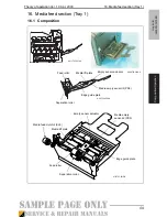
Страница 23: ... section Tray 1 16 1 Composition A0EAT2C503AA A011T2C507AA 4138T2C001DB Feed roller Separation roller Media lift plate Empty sensor actuator Media empty sensor 2 PS3 Edge guide plate Media feed clutch 2 CL3 A011T2C050DA Feed roller Media lift plate Empty sensor actuator Media empty sensor 2 PS3 Edge guide plate Separation roller ...

Страница 24: ... lever will be pressed to the feed roller The media feed clutch will rotate the feed roller to activate the lock release lever pressed to the feed roller and the media lift plate will be unlocked The media lift plate media stack is pressed against the feed roller The media lift plate media stack is pressed upward by the springs at all times 4138T2C002DB Intermediate transport motor M3 Media feed c...

Отзывы: