background image

64

Assembly Completion

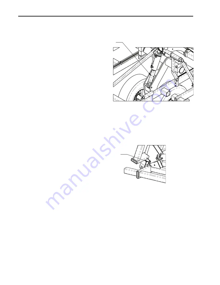
After assembly is complete, charge the wheel lift cylinders with a tractor or hydraulic unit, fully 

extending and retracting the cylinders several times.  Hold the hydraulic lever open at the end of the 

stroke to purge the air from the system. Fully extend the lift cylinders and install the transport safety 

locks onto the center lift cylinders.

Final Inspection

When the machine is fully assembled, verify all nuts, bolts and other connections are secure.  Be 

sure to read the Owners Manual before attempting to operate the unit.  The Owners Manual provides 

important instructions and safety precautions that must be followed before attempting to hook up 

and move the unit after assembly.

��������������

The wing fold cylinders must be charged with oil before attempting to fold the cultivator.  

Disconnect the cylinder rod clevis from the wings and block up the cylinder.  Extend and retract the 

cylinders several times with a tractor or hydraulic unit, holding the lever at the end of the stroke to 

purge the air from the system.  After fold cylinders are charged, re-connect them to the wings.

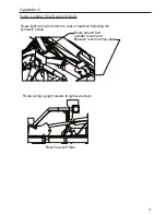
Slowly fold the wings to the transport position.  Insert the wing lock safety pins.

CAUTION:

 ALWAYS INSTALL 

THE TRANSPORT LOCK 

ONTO THE CENTER LIFT 

CYLINDERS WHEN THE 

IMPLEMENT IS PLACED IN 

THE RAISED POSITION FOR 

TRANSPORT, MAINTENANCE 

OR STORAGE.  Secure with the 

pin and lock clip provided.

���������

����������

CAUTION:

  Never transport the implement on public road ways without installing the transport 

safety chain and SMV sign.

Refer to the Owners Manual for further safety information before attempting to operate or service 

the unit.

CAUTION:

  ALWAYS 

INSTALL THE WING LOCK 

SAFETY PINS WHEN THE 

IMPLEMENT IS FOLDED FOR 

TRANSPORT, MAINTENANCE 

OR STORAGE.

Содержание 8200 DF Series

Страница 1: ...ator 42 5 768244901 8244 Field Cultivator 44 5 768246901 8246 Field Cultivator 46 5 768248901 8248 Field Cultivator 48 5 760000229 Revision 7 Serial No 411391 current Model may not be exactly as shown...

Страница 2: ...arts 26 Wing Lift Cylinder Linkage Assembly 28 Outer Wing Assembly 30 Outer Fold Cylinder Assembly 32 Outer Wing Rockshafts and Linkages 34 Wing Fold Stands 34 VibroTine Assembly Option 36 C Shank Ass...

Страница 3: ...uct The Owners Manual will provide you with further instructions on the proper Field Settings Adjustments and Maintenance Procedures for Safe Operation of the unit If optional equipment or attachments...

Страница 4: ...bly Instructions Hardware included in bag 760033040 Connect center frames as shown using parts listed on next page Place center frames on steel shop stands during assembly until lift hydraulics are in...

Страница 5: ...no Qty Description 1 760032000 1 Center Mainframe Wdmt LH 2 760032001 1 Center Mainframe Wdmt RH 3 760032063 1 Leveling Pivot Linkage Mount 4 600356107 2 Bolt 5 8 X 3 GR 5 5 600356023 16 Bolt 5 8 X 1...

Страница 6: ...frame as shown using parts listed on next page Spindles and wheels can be installed to rockshaft assembly before or after rockshaft is attached to the frame IMPORTANT Install wheels to the spindles s...

Страница 7: ...60031189 8 Center Rockshaft Block 3 7600355102 8 Bolt 3 4 X 9 1 2 GR 8 4 600366024 8 Nut Toplock 3 4 5 7600473119 4 8 X 8 Hub G60 8 Spindle Assembly 6 600355052 4 Bolt 5 8 X 4 1 2 GR 8 7 600366031 4 N...

Страница 8: ...8 Center Rockshaft Parts...

Страница 9: ...31 4 Bearing JLM506849 7 76301137 4 Bearing Cup JLM506810 8 76301135 4 Bearing Cup LM501310 9 76301129 4 Bearing LM501349 10 600473052 4 Washer EMI 8000 11 600366012 4 Slotted Nut 1 UNF 12 76301230 4...

Страница 10: ...10 Instructions Hardware included in bag 760033040 Attach fold cylinder mounts and cross brace as shown using hardware on next page Fold Cylinder Mount Assembly...

Страница 11: ...Cylinder Base Mount Wdmt 2 760032051 1 Center Frame Cross Brace Wdmt 3 760032050 1 Front Fold Cylinder Base Mount Wdmt 4 600355028 16 Bolt 5 8 X 2 GR 8 5 600381052 16 Flat Washer 5 8 SAE 6 600366031...

Страница 12: ...sing parts listed on next page On base end of cylinders use pins which come with cylinders pins shown are for repair only Install leveling linkage as shown in image A This will give the rear of the ma...

Страница 13: ...nkage Tube Wdmt 4 600356101 2 Bolt 1 X 5 GR 5 5 600366032 8 Nut Toplock 1 6 7600383204 2 Pin 1 75MM 7 600381018 2 Flat Washer 1 8 600383117 2 Ring Cotter Clip 1 9 600356029 4 Bolt 1 X 5 1 2 GR 5 10 76...

Страница 14: ...listed on next page Bracket should be placed 8 from center frame rail Assemble striker bolt and spring to outer tube wdmt Insert inner tube through outer tube and connect together with crank Attach d...

Страница 15: ...Lockwasher 5 16 8 600365007 2 Nut 5 16 9 601140555 1 Striker Bolt 3 8 X 3 10 601140556 1 Striker Spring 11 600366028 1 Nut Toplock 3 8 12 760032022 1 Single Point Outer Tube Wdmt 13 760032038 1 Singl...

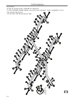
Страница 16: ...ble on all double fold models except the 8238 The 8238 requires the light tubes to be mounted at the narrowest position Disconnect safety pin chain from split ring and route chain through base of plat...

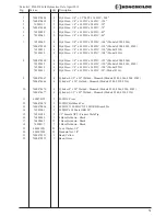
Страница 17: ...t 3 8 X 2 X 3 6 600382051 8 Lockwasher 3 8 7 600365008 8 Nut 3 8 8 601140845 1 SMV Sign 9 760031216 2 4 1 4 x 8 Cylinder Safety Lock 10 600383141 2 Clevis Pin 3 8 X 3 11 600383142 2 Hair Pin 3 32 X 1...

Страница 18: ...onents can be installed before or after the wing frames have been assembled to the center frame Attach hitch turnbuckle and components to center frame as shown using hardware listed on next page Turnb...

Страница 19: ...clevis 11 600355025 2 Bolt 1 X 7 GR 8 12 600355027 1 Bolt 1 X 8 GR 8 13 600366032 4 Nut Toplock 1 14 600461011 1 ASAE Safety Chain Assembly 15 760032039 1 Hydraulic Hose Support Wdmt 16 600356020 2 B...

Страница 20: ...Bolt together wing frames as shown using hardware listed on next page and then attach to center frame Use steel shop stands to support the wings until lift and fold hydraulics are installed and worki...

Страница 21: ...Inner Wing Frame Wdmt RH DF Models 8248 8246 not shown 760032074 1 3 5 Innner Wing Frame Wdmt RH DF Models 8244 8242 8240 not shown 760032072 1 2 5 Innner Wing Frame Wdmt RH DF Model 8238 not shown 76...

Страница 22: ...in bag 760033043 Attach fold cylinders to center and wing frames as shown using parts listed on next page On base end of cylinders use pins which comes with cylinders pins shown are for repair only In...

Страница 23: ...ription 1 7600474667 4 Cylinder 4 1 2 X 30 Welded Monarch Models 8248 8246 8244 8242 7600474666 4 Cylinder 4 X 30 Welded Monarch Models 8240 8238 8236 2 600383136 4 Pin 1 85MM 3 600381018 8 Flat Washe...

Страница 24: ...indles and wheels can be installed to rockshaft assembly before or after rockshaft is attached to the frame IMPORTANT Install wheels to the spindles so the wheel rims are offset toward the wheel arms...

Страница 25: ...760031218 8 Wing Rockshaft Block 760031083 Wing Rockshaft Block Old used w o sleeves 3 600355026 8 Bolt 3 4 X 6 1 2 GR 8 4 600366024 8 Nut Toplock 3 4 5 763011121 4 6 X 6 Hub G35 6 Spindle Assembly 6...

Страница 26: ...26 Wing Rockshaft Parts...

Страница 27: ...301129 2 Bearing LM501349 7 76301135 2 Bearing Cup LM501310 8 76301134 2 Bearing Cup LM67010 9 76301132 2 Bearing Cone LM67048 10 600381009 2 Flat Washer 3 4 11 76301153 2 3 4 16 UNF Slotted Nut 12 76...

Страница 28: ...and linkage as shown using parts listed on next page On base end of cylinders use pins which comes with cylinders pins shown are for repair only Adjust eyebolt to initial setting of about 4 3 8 as sho...

Страница 29: ...s 8248 8246 8244 8242 7600474665 2 Cylinder 3 1 2 X 8 Welded Rephase Monarch Models 8240 8238 8236 2 760032057 2 Cylinder Linkage Wdmt 3 760032059 2 Leveling Linkage Tube Wdmt 4 600356101 4 Bolt 1 X 5...

Страница 30: ...ing frames as shown using hardware listed on next page 8248 is only model with two piece outer wing and then attach to center frame Use steel shop stands to support the wings until lift and fold hydra...

Страница 31: ...1b 760032046 1 2 5 Outer Pivot Wing Frame Wdmt RH Model 8248 not shown 760032082 1 7 Outer Wing Frame Wdmt RH DF Models 8246 8244 not shown 760032080 1 6 Outer Wing Frame Wdmt RH DF Model 8242 not sho...

Страница 32: ...033044 Attach fold cylinders to intermediate and outer wing frames as shown using parts listed on next page On base end of cylinders use pins which comes with cylinders pins shown are for repair only...

Страница 33: ...8248 8246 8244 8242 7600474677 4 Cylinder 3 1 2 X 20 Welded Monarch Models 8240 8238 8236 2 760032087 4 Float Linkage Wdmt Models 8248 8246 8244 8242 760032089 4 Float Linkage Wdmt Long Models 8240 82...

Страница 34: ...inkages to outer wings in the same manner as the intermediate wings See pages 24 29 Outer Wing Rockshafts and Linkages Wing Fold Stands Instructions Hardware included in bag 760033045 Attach wing stan...

Страница 35: ...gust 2014 Fig Part no Qty Description 1 760032052 4 Wing Stand Wdmt Short Models 8248 8246 8244 8242 760032088 4 Wing Stand Wdmt Tall Models 8240 8238 8236 2 7600373131 8 U Bolt 1 2 X 4 X 5 25 3 60038...

Страница 36: ...uts in Tine Harrow Layout Manual 760000231 for proper placement 1 Place coil clamp and bolt onto frame 2 Insert tine coil assembly through clamp and bolt to frame Tighten bolt so that front of clamp b...

Страница 37: ...5 8 UNC 7 600373076 1 Bolt 5 8 x 1 3 4 UNF Gr 8 8 600366025 1 Nut Toplock 5 8 UNF 9 101002004 1 4 8mm Heavy Duty Sweep 10 101002003 4 6mm Sweep 11 101002002 2 3 4 6mm Heavy Duty Goosefoot Share 12 101...

Страница 38: ...embly 2 Detach spring from top bolt and install c shank assembly on implement with u bolt 3 Re attach spring with top bolt and tighten down until there is only a 1 2 gap between the spring insert and...

Страница 39: ...ck 5 8 11 600365013 1 Jam Nut 5 8 12 600366030 1 Nut Toplock 1 2 13 600366028 1 Nut Toplock 3 8 14 600356023 1 Bolt 5 8 X 1 3 4 GR 5 15 600356003 1 Bolt 1 2 X 3 GR 5 16 600373072 1 Bolt 5 8 X 5 Full T...

Страница 40: ...installed assemble gauge wheels to outer front corners of intermediate and outer wing frames as shown using the parts listed on next page Location will vary depending on tine spacing gauge wheel not t...

Страница 41: ...3061 2 Gauge Wheel Arm Assemlby G35 6 Hub single piece tab 601231421 2 Gauge Wheel Arm Assembly Old style with two tabs 6 7600383215 2 Gauge Wheel Pivot Pin 1 7 600381018 4 Flat Washer 1 8 600383117 4...

Страница 42: ...42 Gauge Wheel Assembly Parts 1 2 11 6 7 9 8 10 12 5 3 4 13 14 14 Old Style Arm...

Страница 43: ...ease Fitting 11 600381009 1 Flat Washer 3 4 12 76301153 1 3 4 16 UNF Slotted Nut 13 76101249 1 Cotter Pin 5 23 x 1 3 4 1 601232321 1 Gauge Wheel Arm Weldment Old style w two tabs 2 606001186 1 5000 lb...

Страница 44: ...s Install rear jack bracket onto rear bar of center mainframe with hardware provided It is recom mended to located bracket as near to the center of the cultivator as possible for better stability Rear...

Страница 45: ...DF Rear Jack Assembly Date March 2014 Fig Part no Qty Description 1 760032058 1 Rear Jack Bracket 2 600356134 2 Bolt 1 2 X 5 1 2 GR 5 3 600382053 2 Lockwahser 1 2 4 600365009 2 Nut 1 2 5 601231223 1...

Страница 46: ...ach hydraulic hose tree to fold cylinder base weldment using hardware listed on next page Locate tree directly above the inner frame rail on the left mainframe It is recommended to install bulkhead fi...

Страница 47: ...20 1 Fold Cylinder Base Mount Wdmt 2 760031115 1 Hyd Hose Tree 3 7600373129 1 U Bolt 3 8 x 3 x 2 3 4 4 600382051 2 Lock Washer 3 8 5 600365008 2 Standard Nut 3 8 6 7600470474 2 6 MJIC Bulkhead Tee 7 7...

Страница 48: ...cs Instructions Hardware included in bag 760033045 760033016 Connect hydraulic fittings and hoses as shown in this schematic Refer to Appendix A for de tailed routing information Secure hoses with hol...

Страница 49: ...7600470485 1 Hyd Hose 3 8 x 8 FJIC x 8 FJIC 236 Model 8236 9 7600470502 1 Hyd Hose 3 8 x 8 FJIC x 8 FJIC 352 Model 8248 7600470503 1 Hyd Hose 3 8 x 8 FJIC x 8 FJIC 340 Model 8246 7600470504 1 Hyd Hos...

Страница 50: ...cs Instructions Hardware included in bag 760033045 760033016 Connect hydraulic fittings and hoses as shown in this schematic Refer to Appendix A for de tailed routing information Secure hoses with hol...

Страница 51: ...202035 4 Hyd Hose 1 4 x 6 FJIC x 6 FJIC 120 Models 8244 8242 8240 76202010 4 Hyd Hose 1 4 x 6 FJIC x 6 FJIC 108 Model 8238 76202033 4 Hyd Hose 1 4 x 6 FJIC x 6 FJIC 96 Model 8236 9 7600474667 4 Cylind...

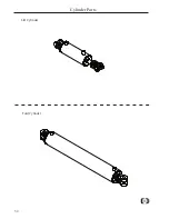
Страница 52: ...52 Cylinder Parts Lift Cylinder Fold Cylinder...

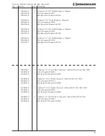
Страница 53: ...3 1 2 X 8 Welded Rephase Monarch 7600474669 Clevis Monarch 493830 7600474671 Seal Repair Kit Monarch 649216 7600474667 2 Cylinder 4 1 2 X 30 Welded Monarch Models 8248 8246 8244 8242 7600474674 Clevis...

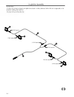
Страница 54: ...ht kit as shown in the schematic below Refer to Appendix A for detailed routing information Secure wiring with cable ties Light Kit Assembly 2 Pin Connector 2 Pin Connector 3 Pin Connector 3 Pin Conne...

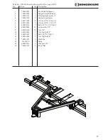
Страница 55: ...te May 2015 Fig Part no Qty Description 760033006 1 8200 Series Light Kit 1 760031240 1 Harness 30 Lead w 7 Pole Ag Plug 2 760031241 1 Harness 11 Y LH 3 760031242 1 Harness 15 Y RH 4 760031243 1 Tail...

Страница 56: ...using u bolts provided Loosely attach the support arm and spacers to cultivator where the two bolts were removed Use the u bolts provided to attach the support arm to the rear hitch and tighten up al...

Страница 57: ...4 760031162 2 Support Arm Spacer 5 600373058 4 U bolt 5 8 X 4 X 5 1 2 6 600373056 2 U bolt 5 8 X 3 X 5 1 2 7 600356116 2 Bolt 5 8 X 3 1 2 GR 5 8 600382054 12 Lockwasher 5 8 9 600365014 12 Nut 5 8 10...

Страница 58: ...ough trimmed opening in rear hitch tube 4 Route hoses over existing hoses and clamps to front of cultivator 5 Secure female couplers 3 to coupler bracket 1 using retaining rings 5 on either side of br...

Страница 59: ...5192 1 Bracket Coupler Mount 2 7600470510 4 Hose 3 8 8MP 8MP 432 LG 3 7600470496 4 Coupler 1 2 Female 8FP Push Pull 4 600470110 4 Coupler 1 2 Male 8FP 5 7600407054 8 Ring Ext Retaining 1 50 x 05 6 760...

Страница 60: ...t arm of rear hitch and down inside arm Note If installing optional hydraulic kit run hoses and harness at same time 3 Disconnect existing left and right wire harnesses running from lights to main har...

Страница 61: ...art no Qty Description 1 760031213 1 Bracket 7 Pole Socket Mount 2 760031214 1 Harness 8 Extension w 7 Pole Socket 3 600356020 2 Bolt 3 8 x 1 GR 5 4 600366028 2 Nut Toplock 3 8 5 600356106 2 Bolt 5 16...

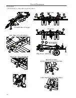
Страница 62: ...62 Decal Placement Instructions Attach decals to clean surface as shown below...

Страница 63: ...djust Decal 5 600475039 4 Wing Safety Decal 6 600475176 2 Decal Wing Fold Lock 7 600475180 6 Yellow Reflective Strip 8 600475179 4 Red Reflective Strip 9 600475178 6 Red Orange Fluorescent Strip 10 60...

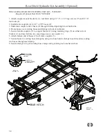
Страница 64: ...e attempting to fold the cultivator Disconnect the cylinder rod clevis from the wings and block up the cylinder Extend and retract the cylinders several times with a tractor or hydraulic unit holding...

Страница 65: ...ingle point Route hoses along mainframe to hydraulic tree 3 8 Hoses on bottom Route hoses from tree to center lift cylinders Route hoses from center lift cylinders to intermediate lift cylinders Allow...

Страница 66: ...ift cylinders to outer wing lift cylinders Allow enough slack in hoses to reach outer wing pivot Route hoses from front cross fittings and rear hydraulic tree to inner fold cylinders Route hoses from...

Страница 67: ...to rear of machine following the hydraulic hoses Route around fold cylinder mount and between rear fold stop plates Rear View Left Side Route wiring up light stands to lights as shown Safety Lighting...

Страница 68: ...68 Appendix B Torque Chart...

Страница 69: ...______________________________________________ ____________________________________________________________ _____________________________________________________________ ______________________________...

Страница 70: ...760000229 May 2015...

Отзывы: