


36
322217/G
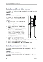
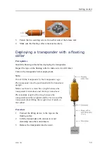
Installing a differential inclinometer
The transponder must have an inclinometer (I) end cap to be able to connect the external
inclinometer sensor.
Prerequisites
Turn on the transponder before installation.
The transponder must have an inclinometer (I) end cap
to be able to connect the external inclinometer sensor.
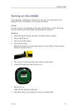
Procedure
1
Place the transponder and transponder rack on the
floor.
2
Mount the transponder in the transponder rack by
fastening the clamps around the transponder.
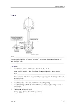
3
Secure the clamps with screws and tighten them
properly.
4
Connect the interface cable to the transponder and
the other end to the external inclinometer.
Always apply grease before mating connectors.
SubConn
®
connectors should not be exposed to
extended periods of heat or direct sunlight. If a
connector becomes very dry, it should be soaked
in fresh water before use.
5
Make sure both units face the same direction.
FWD is moulded into the coating of the sensor
module on the transponder and it is engraved into the top end cap of the sensor unit.
6
Mount the arrangement to the customer’s structure.
7
Adjust the offset values in APOS to make sure the angles are correct.
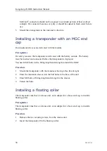
Installing a sea current meter
The transponder must have an sensor interface (Si) end cap to be able to connect the
external sensor.
Prerequisites
Turn on the transponder before installation.
The transponder must have an sensor interface (Si) end cap to be able to connect the
external sensor.
Kongsberg cNODE Instruction Manual
Содержание cNODE Maxi
Страница 1: ...Instruction Manual cNODE Maxi and Midi Transponders Medium Frequency 4000 metres ...
Страница 2: ......
Страница 69: ...322217 G 67 Differential inclinometer arrangement drawing About drawings ...
Страница 70: ...68 322217 G Current meter arrangement drawing Kongsberg cNODE Instruction Manual ...
Страница 98: ... 2019 Kongsberg Maritime ...


