background image

UAB KOMFOVENT we reserve the right to make changes without prior notice

7

C3.1-16-01

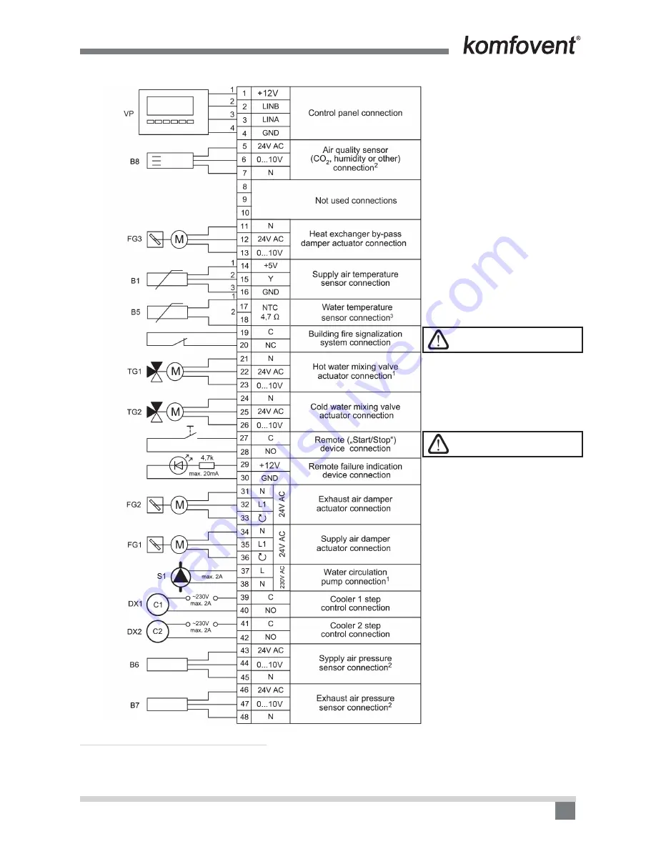
C3-P1 Control System External Elements Connection Diagram


1.3 d Picture

1

 Used only in the units with water heater.

2

 Only in units with EC fans, additional accessories required.

3

 used only in VERSO P 7000 H units.

Normally closed contact.  

Do not connect voltage!

Control contact.  

Do not connect voltage!

Содержание C3.1

Страница 1: ...EN Electrical installation and Operation Manual C3 1 ...

Страница 2: ......

Страница 3: ...me or your household waste disposal service Content 1 ELECTRICAL INSTALLATION MANUAL 4 1 1 Air Handling Units Sections Connection 4 1 2 Electric Power Supply Connection 4 1 3 External Elements Connection 5 1 4 Temperature Sensors Installation 8 1 5 Requirements for the installation of the control panel 8 1 6 Control panel connection 8 2 OPERATION MANUAL 9 2 1 Unit Control 9 2 2 Control panel indic...

Страница 4: ...e is 230 V 50 Hz it is necessary to install the socket with grounding of correspond ing capacity see electric diagram unit If the voltage is 400 V 50 Hz the cable of electrical power supply is connected to the main switch which is located on the unit s outside wall It is necessary to connect earthing Types of cables of connection of electrical power supply are specified in 1 2 Table 1 2 Table Elec...

Страница 5: ...n type B or B Before connecting unit to the electrical power supply it is necessary to check whether earthing has been installed properly 1 3 External Elements Connection In the air handling unit it is provided connection board 1 3 a picture or 1 3 b picture depending on the unit type all external elements are connected to connection board External elements connection diagram is given in the 1 3 c...

Страница 6: ...rnal Elements Connection Diagram 1 3 c Picture 1 Used only in the units with water heater 2 Only in units with EC fans additional accessories required 3 In DOMEKT S VERSO S unit is not used 4 In units with AC fans is not used Control contact Do not connect voltage Normally closed contact Do not connect voltage ...

Страница 7: ... Control System External Elements Connection Diagram 1 3 d Picture 1 Used only in the units with water heater 2 Only in units with EC fans additional accessories required 3 used only in VERSO P 7000 H units Normally closed contact Do not connect voltage Control contact Do not connect voltage ...

Страница 8: ...wing conditions are ensured 1 1 ambient temperature 0 ºC 40 ºC 1 2 relative humidity range 20 80 1 3 protection against dripping of water IP X0 2 Control panel connection is provided through a hole in the back or bottom side 3 The panel can be mounted on a flush mounting box or in any other place just screwing two holes on the fastening surface Do not use any other type or size screws but those th...

Страница 9: ...xtract room air quality Fan operation Energy recovery operation Air heater operation Air cooler operation Weekly operation mode Unit control activation by external contacts see Chapter 2 5 2 5 Alarm signal 2 OPERATION MANUAL 2 1 Unit Control Air handling units control system ensures control of the physical pro cesses that are taking place inside the air handling unit Control system consists of mai...

Страница 10: ... OTK only supply air flow and temperature is indicated 2 4 Operation modes selection Three operation modes are possible one of them user can select directly from control panel main window MODE 1 2 3 for each of them the user can set air flow and temperature OFF mode completely turns off the unit Reset settings MODE 2 Supply air flow 1250 m3 h Extract air flow 1250 m3 h Setpoint 20 C MODE 1 21 9 C ...

Страница 11: ... the notification of existing faults After failure elimination see chapter 2 8 messages are deleted by selecting Delete By clicking on History can be viewed up to 50 registered alarms 2 5 1 2 Detailed information All temperature sensor readings functioning of separate air handling unit ele ments and other detailed information is available in this menu Detailed information Supply air flow 350 m3 h ...

Страница 12: ... will be caused sometimes needed to start the fireplace or such Note After this function has been activated unit will work for the set time period with present exhaust correction After time period is over this function turns off automatically This function is provided only in units with EC fans This function is not available in supply air units OTK 2 5 2 3 Summer night cooling If the room temperat...

Страница 13: ...al signal short circuit on contacts 17 18 1 3 c Pic or 27 28 1 3 d Pic activates Override function and air handling unit starts to operate by the preset parameters If Override function is deactivated then mentioned contacts can be used for remote on off control of the unit see Chapter 2 6 1 Enable Min temperature control Enable Supply flow 1250 m3 h Extract flow 1250 m3 h Setpoint 20 C Override fu...

Страница 14: ... flow in this case discharged air operates as the slave ventilation sys tem and always follows the master one If the supply air requirement in the ventilation system which is assigned as the master system decreases the intensity of discharged air in the slave system is reduced correspondingly by the same percentage If the variable air volume control function is mode is selected the initial calibra...

Страница 15: ... Remote unit operation and failure indication If the information about unit operation mode is requested when unit is operating and when is not indication device for ex bulb must be connected to the contacts 33 35 see chapter 1 3 c Picture In the connection board see chapter 1 3 are provided contacts 33 34 see chapter 1 3 c Picture or 29 30 see chapter 1 3 d Picture which are intended for connectio...

Страница 16: ...Electric heater overheating protection is on To restore protection it is possible only after pressing RESET button which is located on the heater Return water low temperature Return water temperature in water heater dropped lower allowable level Check circulation pump and heating system con dition heating valve actuator performance Frost possibility Temperature of the air passing through plate hea...

Страница 17: ...perate and failure message is indicated 3 SAFETY REQUIREMENTS To avoid accidents and or unit damage only a trained technician must carry out the connection The appropriate Personal Protective Equipment PPE attire is worn relative to the operation being carried out Electrical equipment is rated connected and earthed in accordance with CE regulations Before performing any jobs inside the unit make s...

Страница 18: ......

Страница 19: ......

Страница 20: ...ma www microclima hr HU AIRVENT Légtechnikai Zrt www airvent hu Gevent Magyarország Kft www gevent hu Merkapt www merkapt hu IR Fantech Ventilation Ltd www fantech ie IS Blikk Tækniþjónustan ehf www bogt is Hitataekni ehf www hitataekni is NL Ventilair group www ventilairgroup com DECIPOL Vortvent www vortvent nl NO Ventistål AS www ventistal no Thermo Control AS www thermocontrol no PL Ventia Sp ...

Отзывы: