background image

MAINTENANCE

SERVICE PROCEDURE

4-43

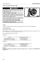
CHECK BEFORE STARTING

4

For the following items, see “CHECK BEFORE STARTING (3-69)“.

q

Checking with machine monitor

q

Check dust indicator

q

Drain water from fuel pre-filter

q

Check coolant level, add coolant

q

Check oil level in engine oil pan, add oil

q

Check brake oil tank level, add oil

q

Check fuel level, add fuel

q

Check electric wiring

q

Check parking brake

q

Check brake pedal

q

Check inflation pressure of tires

q

Check waterproof/fireproof dividing walls

Содержание WA800-3E0

Страница 1: ...cause serious injury or death Operators and maintenance personnel must read this manual before operating or maintaining this machine This manual should be kept inside the cab for reference and periodi...

Страница 2: ......

Страница 3: ...FOREWORD 11...

Страница 4: ...you understand them fully Keep this manual in the storage location for the operation and maintenance manual given below and have all personnel read it periodically If this manual has been lost or has...

Страница 5: ...identally touch the work equipment control levers when they are not locked this may cause a serious injury or death Other signal words In addition to the above the following signal words are used to i...

Страница 6: ...the method of avoiding the hazardous condition is shown inside a circle Komatsu cannot predict every circumstance that might involve a potential hazard in operation and maintenance Therefore the safet...

Страница 7: ...3E0 q Sound pressure level at the operator s station measured according to ISO6394 Static test method simulated work ing cycle WA900 3E0 q Sound pressure level at the operator s station measured acco...

Страница 8: ...e the correct equipment and attachments 2 Maintain the machine according to this manual q Tire pressures for wheeled machines tension of crawler for crawler machines q Brake and steering systems q Con...

Страница 9: ...nsport machines long distances between worksites 8 The following guidelines can be effective to minimize risks of low back pain q Operate the machine only when you are in good health q Provide breaks...

Страница 10: ...ing work For details of the operating procedure see WORK POSSIBLE USING WHEEL LOADER 3 104 FRONT REAR LEFT RIGHT DIRECTIONS OF MACHINE 1 1 Bucket In this manual the directions of the machine front rea...

Страница 11: ...ibility of this machine in the area 1 m from the outside surface of the machine at a height of 1 5 m is shown in the diagram below The hatched area A shows the area where the view is blocked by part o...

Страница 12: ...rom the machine is as shown in the diagram below The hatched areas B show the areas where the view is blocked when mirrors or other aids to visibility are installed as standard Please be fully aware t...

Страница 13: ...stributor of the following items PRODUCT IDENTIFICATION NUMBER PIN MACHINE SERIAL NO PLATE 1 On the center right of the front frame The design of the nameplate differs according to the territory EPA R...

Страница 14: ...right of maintenance monitor TABLE TO ENTER SERIAL NO AND DISTRIBUTOR 1 Machine serial No Engine serial No Product Identification Number Manufacturers name Address KOMATSU LTD 3 6 Akasaka Minato ku 1...

Страница 15: ...FOREWORD NECESSARY INFORMATION 1 13 MACHINE SERIAL NUMBER PLATE Model Serial Number Manufacturing year Weight Engine power Product Identification Number Manufacturer...

Страница 16: ...DENTIFICATION NUMBER PIN MACHINE SERIAL NO PLATE 1 11 EPA REGULATIONS ENGINE NUMBER PLATE 1 11 POSITION OF SERVICE METER 1 12 TABLE TO ENTER SERIAL NO AND DISTRIBUTOR 1 12 MACHINE SERIAL NUMBER PLATE...

Страница 17: ...DAMAGE TO WIPER ARM BRACKET 3 46 REPLACING CAB WIPER 3 46 DUST INDICATOR 3 47 FUSE 3 47 FUSE CAPACITY AND NAME OF CIRCUIT 3 48 CIRCUIT BREAKER 3 49 SLOW BLOW FUSE 3 49 LUNCH BOX TRAY 3 50 TOOL BOX 3 5...

Страница 18: ...ING OPERATIONS 3 107 PUSHING OPERATION 3 107 LOAD AND CARRY OPERATIONS 3 107 LOADING OPERATIONS 3 108 PRECAUTIONS WHEN HANDLING BLASTED ROCK 3 109 PRECAUTIONS FOR OPERATION 3 121 PERMISSIBLE WATER DEP...

Страница 19: ...HEN ENGINE RUNS 3 146 WHEN ENGINE DOES NOT RUN 3 146 RELEASING PARKING BRAKE 3 147 EMERGENCY TRAVEL OPERATION 3 148 IF BATTERY IS DISCHARGED 3 148 REMOVAL AND INSTALLATION OF BATTERY 3 148 PRECAUTIONS...

Страница 20: ...4 22 CHECK CLEAN OR REPLACE AIR CLEANER ELEMENT 4 22 CLEAN INSIDE OF COOLING SYSTEM 4 24 CHECK TRANSMISSION OIL LEVEL ADD OIL 4 28 CHECK AXLE OIL LEVEL ADD OIL 4 29 CLEAN AXLE CASE BREATHER 4 29 CLEA...

Страница 21: ...OF ENGINE AIR INTAKE PIPING CLAMPS FOR LOOSENESS 4 68 EVERY 2000 HOURS SERVICE 4 69 CHANGE OIL IN HYDRAULIC TANK REPLACE HYDRAULIC FILTER ELEMENT 4 69 CLEAN HYDRAULIC TANK STRAINER 4 72 REPLACE HYDRAU...

Страница 22: ...SING SYSTEM 6 4 METHOD OF ADJUSTING DISCHARGE FROM INJECTOR 6 11 METHOD OF SETTING TIMER 6 13 METHOD OF CHARGING WITH GREASE 6 16 MACHINE EQUIPPED WITH COUPLER 6 16 MACHINE NOT EQUIPPED WITH COUPLER 6...

Страница 23: ...Please be sure that you fully understand this manual and the precautions discribed in this manual and the safety labels on the machine When operating or servicing the machine always follow these prec...

Страница 24: ...UTIONS FOR ATTACHMENTS OPTIONS 2 172 UNAUTHORIZED MODIFICATION 2 182 SAFETY AT WORKSITE 2 182 WORKING ON LOOSE GROUND 2 182 DO NOT GO CLOSE TO HIGH VOLTAGE CABLES 2 192 ENSURE GOOD VISIBILITY 2 192 PR...

Страница 25: ...352 ACCUMULATOR 2 362 PERSONNEL 2 362 ATTACHMENTS 2 362 WORK UNDER THE MACHINE 2 372 NOISE 2 372 PRECAUTIONS WHEN USING HAMMER 2 372 REPAIR WELDING 2 372 REMOVING BATTERY TERMINAL 2 372 PRECAUTIONS W...

Страница 26: ...he correct place and always keep them clean When cleaning them use soap and water Do not use organic solvents or gasoline These may cause the safety labels to peel off If the safety labels are damaged...

Страница 27: ...SAFETY SAFETY LABELS 2 5 LOCATION OF SAFETY LABELS 2...

Страница 28: ...pped machine q Lower working device to the ground move safety lever to lock position and take engine key with you before leaving machine 3 Caution when traveling in reverse WARNING To prevent SEVERE I...

Страница 29: ...distance from electric power lines 5 Do not enter 09162 C0641 q Sign indicates a crush hazard between the articulating parts of the vehicle q Keep away from the vehicle when it is moving 6 Caution fo...

Страница 30: ...aulic tank to cool before removing cap 8 Caution when oil is at high temperature 09653 A0641 q Sign indicates a burn hazard from spurting hot water or oil if radiator or hydraulic tank is uncapped whi...

Страница 31: ...when the working device is raised 11 Do not open when engine is running sign 09667 A0880 q Sign indicates a hazard of rotating parts such as belt q Turn off before inspection and maintenance 12 Do no...

Страница 32: ...A057B q There is the hazard of explosion causing injury q Do not disassemble the accumulator make holes in it weld it cut it hit it roll it or bring it near flame 15 Warning for battery WARNING Keep...

Страница 33: ...chine until the problem has been corrected CLOTHING AND PERSONAL PROTECTIVE ITEMS q Do not wear loose clothing and accessories There is a hazard that they may catch on control levers or other protrudi...

Страница 34: ...e machine is still dirty with mud or oil there is a hazard that you will slip and fall or that dirt or mud will get into your eyes Always keep the machine clean INSIDE OPERATOR S COMPARTMENT q When en...

Страница 35: ...teering lock lever 3 to LOCK position L then stop the engine If you accidentally touch the control levers when they are not locked there is a hazard that the machine may sud denly move and cause serio...

Страница 36: ...d if there is any oil grease or mud on them wipe it off immediately In addition repair any damage and tighten any loose bolts q Do not get on or off the machine while holding tools in your hand PRECAU...

Страница 37: ...event burns from hot water or steam spurting out when checking or draining the coolant wait for the water to cool to a temperature where it is possible to touch the radi ator cap by hand before starti...

Страница 38: ...oil use a non flammable oil Diesel oil and gasoline may catch fire so do not use them q Put greasy rags and other flammable materials into a safe container to maintain safety at the work place q Do n...

Страница 39: ...rgy q If ROPS is modified by welding or drilling holes in it its strength may be reduced If you want to make any modifi cation consult your Komatsu distributor q If ROPS is damaged or deformed by fall...

Страница 40: ...r locations Be careful not to sever or damage any of these lines q Take necessary measures to prevent any unauthorized person from entering the operating area q In particular if you need to operate on...

Страница 41: ...rtment until it has been con firmed that the electricity has been shut off Also do not let anyone near the machine ENSURE GOOD VISIBILITY This machine is equipped with mirrors to improve the visibilit...

Страница 42: ...nals and signs before starting work EMERGENCY EXIT FROM OPERATOR S CAB Machines equipped with a cab have doors on the left and right sides If the door on the one side does not open escape from the doo...

Страница 43: ...around the movable parts of the accelerator pedal or brake pedal and check that the pedals work properly q Adjust the operator s seat to a position where it is easy to carry out operations and check t...

Страница 44: ...checks move the machine to a wide area where there are no obstructions and operate slowly Do not allow anyone near the machine q Always fasten your seat belt q Check the operation of travel steering a...

Страница 45: ...ground surface and cause the machine to lose its balance or may damage the machine or structures in the area q Avoid traveling over obstacles when possible If the machine has to travel over an obstacl...

Страница 46: ...steel plates with low speed Even with slight slopes there is a hazard that the machine may slip q If the engine stops depress the brake pedal immediately lower the bucket to the ground and apply the...

Страница 47: ...y hit the dump truck and cause serious injury or property damage PRECAUTIONS WHEN OPERATING q When using the machine to prevent the machine from overturning due to overloading and to avoid damage to t...

Страница 48: ...brakes to overheat and fail q Do not depress the brake pedal repeatedly if not necessary q When traveling downhill use the braking force of the engine and always use the right brake pedal at the same...

Страница 49: ...work equipment lock lever 1 to LOCK position L turn parking brake switch 2 ON set steering lock lever 3 to LOCK position L then stop the engine q Always close the operator s cab door and use the key...

Страница 50: ...Run the engine at low idling and operate slowly at low speed q Never correct your steering on the ramps If necessary drive off the ramps correct the direction then enter the ramps again q When loadin...

Страница 51: ...mount of water q If acid gets into your eyes flush them immediately with large amount of water and seek medical attention q Before working with batteries turn the starting switch to the OFF position A...

Страница 52: ...em machine There is a hazard that the machine will move when the power is connected q Be sure to connect the positive cable first when install ing the booster cables Disconnect the negative cable grou...

Страница 53: ...g has ample strength for the weight of the machine being towed q Never use a wire rope which has cut strands A reduced diameter B or kinks C There is danger that the rope may break during the towing o...

Страница 54: ...ol lever while you are performing ser vice or maintenance you could suffer serious injury or property damage KEEP WORK PLACE CLEAN AND TIDY q Do not leave hammers or other tools lying around in the wo...

Страница 55: ...to the ground and stop the engine q After stopping the engine turn the starting switch to the ON position operate work equipment control lever 1 fully in the RAISE and LOWER directions 2 or 3 times to...

Страница 56: ...ng If maintenance must be carried out with the engine running carry out the operation with at least two workers and do as follows q One worker must always sit in the operator s seat and be ready to st...

Страница 57: ...ke switch 3 ON to prevent the machine from moving q Do not touch any control levers If any control lever must be operated give a signal to the other workers to warn them to move to a safe place PROPER...

Страница 58: ...torch q Do not hit or roll the accumulator or subject it to any impact q When disposing of the accumulator the gas must be released Please contact your Komatsu distributor to have this work performed...

Страница 59: ...et teeth cutting edges or bearings are hit with a hammer there is a hazard that pieces might be scattered and cause injury Always wear safety glasses and gloves q When hitting pins or bucket teeth the...

Страница 60: ...skin or cause blindness if it con tacts your eyes directly If you are hit by a jet of high pres sure oil and suffer injury to your skin or eyes wash the place with clean water and consult a doctor imm...

Страница 61: ...glasses dust mask gloves and other protective equipment PERIODIC REPLACEMENT OF SAFETY CRITICAL PARTS q In order for the machine to be operated safety for a long time it is necessary to add oil and t...

Страница 62: ...the rim parts do not fit the tire there is a problem with the tire or rim parts Always contact your Komatsu distributor for repairs q If the rim parts are not fitted properly when the tire is being pu...

Страница 63: ...OPERATION 13 WARNING Please read and make sure that you understand the SAFETY section before reading this section...

Страница 64: ...IEW OF MACHINE 3 1 Bucket 8 Turn signal lamp 2 Bell crank 9 Rear wheel 3 Bucket cylinder 10 Front wheel 4 Lift arm 11 Lift cylinder 5 Front working lamp 12 Rear working lamp 6 Head lamp 13 Rear combin...

Страница 65: ...nance monitor 9 1st 2nd 3rd speed indicator lamp for auto shift 29 Lunch box tray 10 Front wiper switch 30 Engine service monitor 11 Rear wiper switch 31 Machine monitor mode selector switch 1 12 Lamp...

Страница 66: ...GENERAL VIEW OPERATION 3 4...

Страница 67: ...pressure caution pilot lamp 9 Transmission cut off switch pilot lamp 24 Engine oil pressure caution pilot lamp 10 Transmission auto shift manual selection 25 Engine oil level caution pilot lamp switch...

Страница 68: ...tant to completely understand methods of operating the equipment and the meanings of the displays MACHINE MONITOR 3 MONITOR SYSTEM 3 A Meter display portion G Meter display portion B Warning display p...

Страница 69: ...METER DISPLAY PORTION Meter display portions A C D F G J K consist of the following For details see METER DISPLAY PORTION 3 15 Central check lamp CHECK Central caution lamp CAUTION Warning pilot lamp...

Страница 70: ...ometer displays 88 The transmission shift indicator displays 8 Finally the buzzer sounds twice intermittently beep beep to show that the monitor check is completed If any monitor does not light up the...

Страница 71: ...on lamp CAUTION 8 Air cleaner clogging caution pilot lamp Left Right 3 Engine water level caution pilot lamp 4 Engine oil level caution pilot lamp 9 Transmission oil filter pilot lamp 5 Brake oil pres...

Страница 72: ...ity in the engine water level the central check lamp will go out when the engine is started but instead of this the central caution lamp will flash and the alarm buzzer will sound intermittently q If...

Страница 73: ...w the warning pilot lamp and central CAUTION lamp will flash and the alarm buzzer will sound intermittently If the monitor lamps flash stop the engine check the level of the coolant in the radiator an...

Страница 74: ...e brake accumulator It does not indicate any abnormality ENGINE OIL PRESSURE CAUTION PILOT LAMP This lamp 6 warns the operator that the engine lubricating oil pressure has dropped If it flashes stop t...

Страница 75: ...flashes replace the filter element EMERGENCY STEERING PILOT LAMP If equipped This lamp 10 indicates that the engine has stopped when the machine is traveling or there is any abnormality in the pump ci...

Страница 76: ...tarting switch is at the ON position this lamp should light up for approx 2 sec onds and then go out If there is any abnormality with the engine the lamp lights up or flashes If the lamp lights up or...

Страница 77: ...equipped 5 Transumission cut off pilot lamp 13 Remote positioner LOWER set pilot lamp 6 Turn signal pilot lamp if equipped 7 Transmission auto shift manual selector pilot lamp 14 Auto greasing pilot l...

Страница 78: ...f the pre heating status of the electrical intake air heater This lamp lights up when the starting switch is turned to the ON position and goes out when the pre heating is completed The time that it r...

Страница 79: ...auto shift manual selector switch is operated and the transmission shift is changed to manual mode When the lamp is lighted up the speed range can be changed by operating the shift up shift down switc...

Страница 80: ...event seizure by preventing operation if oil is not carrying out lubrication of parts after periodic maintenance has been carried out or after the machine has been out of use for a long period REMOTE...

Страница 81: ...lamp 13 lights up flashes or goes out when the remote positioner LOWER stop position is set or the sensor is adjusted For details see REMOTE POSITIONER 3 101 AUTO GREASING PILOT LAMP If equipped This...

Страница 82: ...amp flash if the second segment of the red range also lights up the lamps flash and the alarm buzzer sounds intermittently TORQUE CONVERTER OIL TEMPERATURE GAUGE This meter 17 shows the torque convert...

Страница 83: ...range If the forward reverse selector switch is at the Neutral position the indicator displays N If the forward reverse selector switch is at the FORWARD or REVERSE position the transmission speed ran...

Страница 84: ...EXPLANATION OF COMPONENTS OPERATION 3 22 SWITCHES 3...

Страница 85: ...ey to the START position START position This is the engine start position Keep the key at this position during cranking Immediately after starting the engine release the key It will automatically retu...

Страница 86: ...ake pedal acts as normal brake like right brake pedal ON Left brake pedal acts as normal brake but also switches transmission to NEUTRAL If the switch is turned to ON the transmission cut off pilot la...

Страница 87: ...lamp to the ON position then operate the switch for the working lamp If the side clearance lamp or head lamp are not at the ON position the working lamps will not light up For details see LAMP SWITCH...

Страница 88: ...ect the speed range when traveling The 1st 2nd 3rd speed indicator lamp go out When the switch is set to the ON position the transmission auto shift manual selector pilot lamp lights up REMARK The spe...

Страница 89: ...light up in addition to lamps at posi tion B TURN SIGNAL SWITCH Use this switch 9 to operate the turn signal lamp Position L Left turn switch is operated to left Position R Right turn switch is opera...

Страница 90: ...simply by pressing shift up switch 11 or shift down switch 12 Use 1st or 2nd speed for operations and 3rd speed when traveling Auto shift Of the 3 gear speeds in FORWARD and REVERSE automatic shifting...

Страница 91: ...s flash Position B OFF REMARK When this switch is turned to the ON position the turn signal lamp and turn signal pilot lamp flash KICKDOWN SWITCH When the speed range is 2nd press this switch 15 on th...

Страница 92: ...her liquid is sprayed out Position B OFF Position C Wiper is operated Position D Washer liquid is sprayed out wiper is operated CIGARETTE LIGHTER This is used to light cigarettes After cigarette light...

Страница 93: ...machine is left with the engine stopped but the parking brake switch is at the OFF position or if the starting switch is at the OFF position and the parking brake switch is set to the OFF position whe...

Страница 94: ...When closing the window glass be careful not to get anyone s hands or head caught There is danger of serious injury if anyone is caught in the window glass CAUTION After fully opening or fully closin...

Страница 95: ...n traveling up or down hills or when carrying out grading use this to set the travel speed to the desired position REMARK It is possible to shift up or down from the fixed speed range by operating the...

Страница 96: ...de For details see REMOTE POSITIONER 3 101 REMOTE POSITIONER RAISE LOWER SELECTOR SWITCH If equipped Use this switch 29 to actuate the remote positioner Each time the switch is pressed the remote posi...

Страница 97: ...tion Press here to go on to the next screen or to move the cursor forward or to increase the number when entering numerals Position Press here to go back to the previous screen or to move the cursor b...

Страница 98: ...DALS 3 1 Steering lock lever 6 Brake pedal 2 AJSS lever 7 Accelerator pedal 3 Work equipment lock lever 8 AJSS lever front rear adjustment knob 4 Bucket control lever 9 Right armrest adjustment lever...

Страница 99: ...always set the steering lock lever to LOCK position L This lever 1 is the lock device for the AJSS lever Push the steering lock lever to the left to lock it AJSS LEVER WARNING When the engine is runni...

Страница 100: ...position L q When operating the work equipment lock lever be careful not to touch work equipment control lever A This lever 3 is the lock device for the work equipment control levers Push the work eq...

Страница 101: ...he lever stops at that position detent position When the lift arm reaches the maximum height the lever returns to the HOLD position Position B HOLD The lift arm is stopped and held in position Positio...

Страница 102: ...ght brake pedal for normal braking operations LEFT BRAKE PEDAL The left brake pedal operates the wheel brakes When the transmission cut off switch is in the ON position and if this brake pedal is depr...

Страница 103: ...ossible to move the AJSS lever within a range a to the front and rear of 160 mm 16 mm x 10 stages In addition when getting on or off the machine it is also possi ble to move the AJSS lever 150 mm to t...

Страница 104: ...itor If this operation adjustment is carried out while the machine is moving it may lead to a serious accident or personal injury This lever allows the main monitor to be tilted forward or back ward R...

Страница 105: ...is not inserted fully into the starting switch and is turned the key may break 2 Turn the starting switch key counterclockwise and bring the rotor groove in line with the aligning mark on the cap Tur...

Страница 106: ...e front frame and rear frame so that machine does not articulate LOCK position L Always set to this position when transport ing or lifting the machine For maintenance set to this position if necessary...

Страница 107: ...ON position the engine will not start FUEL STOP LEVER 3 This is used when there is any abnormality such as when the engine cannot be stopped even if the starting switch is turned to the OFF position...

Страница 108: ...r arm to the front check that the wiper blade is hanging free When angling the wiper arm to the front such as when wiping the glass clean if the wiper arm is angled with the wiper blade locked to the...

Страница 109: ...ghts up to inform the operator that the air cleaner needs to be cleaned After cleaning press the reset button to cancel the lamp For details of the method of cleaning see CLEANING OR REPLACING OUTER E...

Страница 110: ...ment panal 11 10A Work equipment positioner 12 20A Starting switch 13 20A Hazard lamp 14 10A Spare 15 10A Auto greasing A if equipped Front of machine No Fuse capacity Name of circuit 1 20A Front work...

Страница 111: ...vier than when operating it in normal conditions There is no difference in the height of the reset button between the condition when that the circuit is cut off or the condition when it has been reset...

Страница 112: ...nstalled under the lunch box so do not place any wireless device on top of the lunchbox For the way of installing the wireless set see HANDLING WIRELESS 3 65 TOOL BOX 3 The tool box is installed in th...

Страница 113: ...nd select the appropriate power source Mistaken use such as using 24V as the power source for 12V equipment will cause failure of the equipment q When using the electric power source do not install an...

Страница 114: ...ind buttons 3 Bass control knob 10 Preset buttons 4 Treble control knob 11 Metal tape button 5 Loudness button 12 Manual tuning buttons 6 Time radio display selector button 13 Seek tuning buttons 7 Ta...

Страница 115: ...uency is memorized in the auto store REMARK The auto store function cannot be used when the channel dis play is flashing When the display is flashing the preset scan function is being used q Preset sc...

Страница 116: ...e easily by emphasizing the low tone when the low tones are weak Push button Actuated ON Push button again Canceled OFF TIME RADIO DISPLAY SELECTOR BUTTON This button 6 is used to switch between the R...

Страница 117: ...f you press the button pointing in the same direction as the lighted arrow indicating the direction of play the tape will be fast forwarded if you press the button pointing in the opposite direction t...

Страница 118: ...MHz for FM when TUN button is pressed the frequency goes down 9 kHz for AM or 0 1 MHz for FM If the button is pressed down and held the frequency will change continuously SEEK TUNING BUTTONS These but...

Страница 119: ...tion 3 Press manual memory button 2 or seek tuning button 3 4 Press preset button 4 of the number to be preset for 2 seconds while the frequency display is being shown on the display The preset channe...

Страница 120: ...assette when listening to the radio the tape will start to play LISTENING TO CASSETTE TAPE 1 Turn the starting switch ON then turn power switch 1 ON 2 Set the cassette with the exposed portion of the...

Страница 121: ...during operations keep the volume at a level where it is possible to hear other machines q If water gets inside the speaker case or radio auto tuning it may cause a serious problem take care not to l...

Страница 122: ...rflow in four stages It also acts as the main switch for the air conditioner When the OFF switch is pressed the fan stops When the switch is pressed the indicator lamp above the switch lights up to di...

Страница 123: ...t MODE SELECTOR SWITCH This switch 3 is used to select the vents The following five vent modes are available FACE FACE FOOT FOOT FOOT DEF DEF When the switch is pressed the indicator lamp above the sw...

Страница 124: ...witch to set the temperature The settings for each mode are retained in memory even when the starting switch is turned OFF However in the following cases the settings must be reset q When the machine...

Страница 125: ...pre vent the loss of the oil film in various parts of the compressor REMARK If the temperature inside the cab is low the air conditioner may not work In such cases use the recirculated air to warm up...

Страница 126: ...once every hour TEMPERATURE CONTROL When the cooler is on set the temperature so that it feels slightly cool when entering the cab 5 or 6 C lower than the outside temperature This temperature differe...

Страница 127: ...4 places in the steel plate inside the mounting cover Press with your finger to find the open place Make 30 mm holes at 4 places in the interior lining stuck to the cover then install the wireless Mak...

Страница 128: ...eck that there are no cracks excessive wear or play in the work equipment cylinders linkage or hoses If any abnormality is found repair it 2 Remove dirt and dust from around engine battery and radiato...

Страница 129: ...e bolts If loose tighten them 10 Check for loose battery terminals Tighten any loose terminal 11 Check for damage to the seat belt and mounting clamps WARNING Even if there appears to be no abnormalit...

Страница 130: ...handle 15 Inspect tires WARNING If worn or damaged tires are used they may burst and cause serious injury or death To ensure safety do not use the following tires Wear Tires with a tread grooves of l...

Страница 131: ...failure or disconnection Contact your Komatsu distributor for inspec tion CHECK DUST INDICATOR 1 If air cleaner clogging warning pilot lamps left right 1 on the maintenance monitor flash clean the ai...

Страница 132: ...the red display to its original posi tion DRAIN WATER FROM FUEL PRE FILTER 1 Check if any water is accumulated in cap 1 at the bottom of the filter 2 If there is water accumulated in the cap 1 loosen...

Страница 133: ...temperature to go down then turn the cap slowly to release the pressure and remove it carefully 1 Check that the coolant is between the FULL and LOW marks on the sight gauge of sub tank 1 If the leve...

Страница 134: ...make it horizontal before checking 2 Open the engine side cover at the rear left of the machine 3 Take out the dipstick G and wipe off the oil with cloth 4 Fully insert dipstick G into filler pipe F...

Страница 135: ...within sight gauge 1 installed to the side of the brake tank There are two sight gauges top and bottom A When checking 10 hours or more after the engine is stopped use the upper level gauge in the fig...

Страница 136: ...for bleeding the air from the fuel circuit see PROCEDURE FOR BLEEDING AIR 3 144 Be careful not to let the engine run out of fuel and stop If the engine runs out of fuel fill the fuel tank before bleed...

Страница 137: ...peration of the parking brake or the brake does not provide the proper braking effect please contact your Komatsu distributor for adjustment CHECK BRAKE PEDAL Drive the machine forward and check the e...

Страница 138: ...hydraulic pump If any damage or missing parts are found please contact your Komatsu distributor for repairs ADJUSTMENT 3 SEAT ADJUSTMENT WARNING q Park the machine in a safe place and stop the engine...

Страница 139: ...may not rise This does not indicate any abnormality If this happens the air compressor will stop automatically after approx 8 seconds It will also stop if lever 3 is pushed down D Setting seat for we...

Страница 140: ...ee Rear tilt 60 degrees NOTICE If the seat back is reclined too far the seat back may hit the rear glass so use it in a position where it does not contact the glass G Adjusting headrest angle Rotate t...

Страница 141: ...belt is worn or damaged replace it q Fasten the seat belt before starting operations q Always wear the seat belt during operations q Make sure that the left and right belts are not twisted when faste...

Страница 142: ...the operator s seat In particular be careful to adjust so that it is possible to see people on the left and right sides at the rear of the machine WA800 3E0 WA900 3E0 Range of view W right 1500mm 150...

Страница 143: ...ctional selector switch of AJSS lever 2 is at the N position and that the AJSS lever is at the Neutral position When starting the engine if the directional selector switch is not at the N position and...

Страница 144: ...ne monitor system works When the starting switch is turned to the ON position before starting the engine all monitor lamps gauges and central warning lamps will light up for approx 3 seconds the centr...

Страница 145: ...ntil it is warmed up 1 Turn the key in starting switch 1 to the ON position For machines not equipped with a prelube system go on to Step 2 For machines equipped with a prelube system 1 If prelube ind...

Страница 146: ...ng pilot lamp 3 is lighted up leave in this condi tion until it goes out The guideline for the preheating time is as follows In cold areas it varies according to the temperature of the coolant when th...

Страница 147: ...RMING UP OPERATION 3 When the engine cooling water temperature is low after the engine starts up warming up run automatically begins and stops 30 minutes after the engine startup or after the engine c...

Страница 148: ...the initial 100 hours as indicated by the service meter During break in operations follow the precautions described in this manual q Idle the engine for 5 minutes after starting it up q Avoid operatio...

Страница 149: ...o warm up the hydraulic oil Keep the relief time at the TILT position to a maximum of 10 seconds If this is done the hydraulic oil reaches the relief pressure so the oil is warmed up more quickly 4 Af...

Страница 150: ...adually then stop it 1 Run the engine at low idle for about 5 minutes to cool down gradually 2 Turn the key of starting switch 1 to the OFF position to stop the engine 3 Remove the key from starting s...

Страница 151: ...obstacles from the travel path q The rear of the machine is a blind spot so when traveling in reverse be particularly careful to check that it is safe q When starting the machine off on a slope depres...

Страница 152: ...ng lock lever to FREE position F 3 Operate lift arm control lever 3 to set the work equipment to the travel posture shown in the diagram on the right A 70 90 cm 4 Depress right brake pedal 8 and turn...

Страница 153: ...REMARK The speed range after turning the starting switch to the ON position is the final speed range selected by the previ ous operation If the system is shifted from auto shift to manual shift or fr...

Страница 154: ...before shifting gear Shift gear as follows When shifting gear select with transmission auto shift manual selector switch 1 and shift with shift up switch 2 or shift down switch 3 at the head of the A...

Страница 155: ...achine becomes weaker Control when shifting down manual shift Control when shifting down auto shift Operation of shift down switch 3rd 3rd o 2nd 3rd o 1st 2nd o 1st Kick down from F2nd Command from co...

Страница 156: ...FORWARD and REVERSE depress the brake to reduce the travel speed suf ficiently then change the direction of travel Max speed for changing direction 12 km h When switching between FORWARD and REVERSE...

Страница 157: ...er than in areas I and II Control when shifting between F R manual shift Control when shifting between F R auto shift I Gearshifting according to operation of lever II Gearshifting according to operat...

Страница 158: ...ove suddenly and cause a serious accident Before standing up from the operator s seat always set the lock levers for the work equipment control levers and AJSS lever securely to the LOCK position q Wh...

Страница 159: ...s the right brake pedal For details of adjusting the brake pedal depression position see ADJUSTING TRANSMISSION CUT OFF POSI TION 3 98 Raise or lower the pre selected brake pedal depression position t...

Страница 160: ...uzzer will sound beep beep and the cut off position is set Method of returning to default setting 5 After the buzzer sounds in Step 4 of the adjustment proce dure press transmission cut off set switch...

Страница 161: ...ion In addition if the AJSS lever is operated in the opposite direction when the machine is turning there will tend to be a shock and this will create a dangerous situation Whentraveling angle AJSS le...

Страница 162: ...ontrol lock lever 3 is the locking device for work equipment control lever A Lower the work equipment lock lever to set it to the LOCK position Lift arm control lever 1 and bucket control lever 2 can...

Страница 163: ...er is returned to the HOLD position REMOTE POSITIONER 3 If equipped A remote positioner function is available for this machine as an optional part METHOD OF OPERATING REMOTE POSITIONER 1 When remote p...

Страница 164: ...height a position above horizontal Then return the lift arm control lever to the HOLD position and press remote positioner RAISE position set switch 2 Remote positioner RAISE stop display lamp 1 will...

Страница 165: ...positioner RAISE set pilot lamp 4 light up release the switches and set to the sensor adjustment mode 3 The remote positioner LOWER set pilot lamp 3 and remote positioner RAISE set pilot lamp 4 light...

Страница 166: ...p the tire life will be reduced so do not allow the tires to slip during operation LOADING PILED SOIL OR BLASTED ROCK q When loading piled soil or blasted rock drive the machine forward as follows to...

Страница 167: ...anced 4 At the same time as thrusting the bucket into the material raise the lift arm to prevent the bucket from going in too far By raising the lift arm ample traction will be produced by the front t...

Страница 168: ...et facing down more than 8 degrees 1 Set the edge of the bucket facing slightly down CAUTION If the bucket hits the rocks in the ground first a large shock is generated and this may damage the machine...

Страница 169: ...e bucket put the lift arm control lever in FLOAT position level the bucket at ground level and smooth the ground by moving backward PUSHING OPERATION 3 CAUTION Never set the bucket to the DUMP positio...

Страница 170: ...hrust the bucket into the material to be loaded borrow pit crushed rock etc at high speed Do not carry out such digging operations NOTICE q If the tires slip the tire life will be reduced so do not al...

Страница 171: ...ds REMARK As far as possible do not use the transmission cut off function during scraping up operation This will prevent the machine from rolling back PRECAUTIONS WHEN HANDLING BLASTED ROCK 3 If the t...

Страница 172: ...t be transmitted fully to the front wheels so this will reduce the digging force and bring an excessive load to bear on the center hinge pin In addition even with the front wheels the power will not b...

Страница 173: ...e bucket and the ground surface facing down more than 8 the bucket cylinder will be pushed by the pushing force of the machine This will cause the cylinder to retract and the bucket will face down at...

Страница 174: ...dilu tion the bucket cylinders and work equipment will be damaged 4 When the scooping up operation is completed operate the bucket tilt and dump and apply the brakes when traveling in reverse to stabi...

Страница 175: ...ve If the boulder is dropped on the opera tor s compartment there is danger of serious personal injury PIT EXCAVATION Do not try to shave off natural rock roots remaining from blast ing Excessive forc...

Страница 176: ...tionary it will cause wear or cuts in the tires In addition it will reduce the durability of the frame and the undercarriage PROCEDURE FOR OPERATIONS USING V SHAPE LOADING OF DUMP TRUCKS PREPARATIONS...

Страница 177: ...surface is more than 8 when digging or lower ing the roadbed there is danger of damage to the work equipment q Do not load the bucket or scoop up the load with the load on the corner of the bucket or...

Страница 178: ...ought to bear on the machine and this will reduce the service life of the work equipment and frame q Operate the control lever slowly near the end of the bucket tilt operation If the control lever is...

Страница 179: ...ne At this distance the rolling of the tires can prevent wear to the tires In addition keep an angle b of 60 at the intersection between the straight line from the dilution and the straight line from...

Страница 180: ...a transmission cut off system is installed turn the transmission cut off switch to the OFF position and depress the brake but do not raise the bucket In this condition the brake is operated so heat i...

Страница 181: ...n addition there is danger of impact pressure being generated in the hydraulic equipment and causing damage to the hydraulic equipment q When loading the dump truck do not pushed forcibly with the buc...

Страница 182: ...ing between forward and reverse when the machine is stationary If the steering is operated when the machine is stationary it will cause wear or cuts to the tires 1 Switch to R2 and drive in reverse 2...

Страница 183: ...requently on downhill slopes there is danger that the brake will overheat and be dam aged To prevent this use the shift down switch to reduce the gear speed and make full use of the braking force of t...

Страница 184: ...y q Before driving the machine carry out the checks before starting q The most suitable tire pressure travel speed or tire type differ according to the condition of the travel surface Contact your Kom...

Страница 185: ...cool q After traveling for 1 hour stop for 30 minutes Check the tires and other parts for damage also check the oil and coolant levels q Always travel with the bucket empty q Never put calcium chlori...

Страница 186: ...LOCK position then stop the engine 2 Loosen two bolts 1 and adjust mounting bracket 4 of the proximity switch so that the rear tip of angle 2 is in line with the center of the sensing surface of proxi...

Страница 187: ...ke sure that there is no one in the surrounding area before starting the operation q When removing the pins do not stand behind the bucket In addition be extremely careful not to put your foot under t...

Страница 188: ...E BUCKET 3 1 Remove mounting bolt 1 2 Sling the bucket link then pull out bucket link pin 2 Secure the bucket link to the tilt lever with wires 3 Remove mounting bolt 3 4 Pull out and remove bucket hi...

Страница 189: ...After cleaning coat the pin and inside surface of the pin hole with fresh grease 1 Set cord ring 2 on top of lift arm boss 1 as shown in the diagram After completing assembly of the bucket and adjustm...

Страница 190: ...ve of the cord ring with grease before install ing it If the cord ring is installed while the groove is dry force will be applied to the cord ring when the bucket is operated and this will cause damag...

Страница 191: ...fore standing up from the operator s seat always set the lock levers for the work equipment control levers and AJSS lever securely to the LOCK position q When the parking brake switch is turned ON it...

Страница 192: ...brake is applied the transmission is automatically returned to neutral 4 Operate lift arm control lever 5 to lower the bucket to the ground 5 Set work equipment lock lever 7 of lift arm control lever...

Страница 193: ...range speed to allow the engine to cool down before stopping it Check that there are no loose bodywork mounting bolts Check that there are no cracks in the work equipment or bucket LOCKING 3 Always lo...

Страница 194: ...or when replacing the tires It is dangerous to jack up the machine without taking due care TIRE PRESSURE 3 Measure the tire pressure before starting operations when the tires are cool If the tire infl...

Страница 195: ...road When shipped from factory Stockpile Digging Stockpile Digging 45 65 45 46PR L5Rock Standard 45 65 45 46PR L4Rock if equipped 679 0 42 0 47 4 25 4 75 0 47 0 52 4 75 5 25 0 47 0 52 4 75 5 25 0 47 0...

Страница 196: ...G LOAD AND CARRY METHOD 3 When traveling continuously with load and carry operations choose the correct tires to match the operating condi tions or choose the operating conditions to match the tires I...

Страница 197: ...nd dimensions for transportation differ according to the type of tires and type of bucket LOADING UNLOADING WORK 3 WARNING When transporting this machine observe all related laws and regulations Disas...

Страница 198: ...osition L to prevent the front frame and rear frame from articulating 7 Put blocks in front of and behind the wheels and secure the machine with chains or wire rope of a suitable strength to prevent t...

Страница 199: ...he area around or under the machine when it is raised Never try to lift the machine in any posture other than the posture given in the procedure below or using lifting equipment other than in the proc...

Страница 200: ...machine on level ground and do as follows 1 Start the engine make sure that the machine is horizontal then set the work equipment to the travel posture For details see PREPARATIONS FOR MOVING MACHINE...

Страница 201: ...to prevent the front frame and rear frame from articulating 5 Select wire ropes slings spreader bars and other lifting equipment to match the weight of the machine and fit the wire ropes to the lifti...

Страница 202: ...g the coolant or when handling coolant containing antifreeze that has been drained when repairing the radiator please contact your Komatsu distributor or request a specialist company to carry out the...

Страница 203: ...temperatures cover or remove the battery from the machine store the battery in a warm place and install it again the next morning q If the electrolyte level is low add distilled water in the morning...

Страница 204: ...ion in a wide space When doing this do not relieve the pressure in the hydrau lic circuit continuously for more than 5 seconds When the temperature is low do not start the operation of the machine imm...

Страница 205: ...d windows to improve ventilation and prevent gas poisoning q During storage operate and move the machine for a short distance once a month so that a new film of oil will coat moving parts At the same...

Страница 206: ...ual pressure 1 Loosen air bleed plug 1 and 2 at the fuel main filter head 2 Loosen wing nut 5 holding lever 4 of priming pump 3 3 Pump lever 4 to pump out fuel from air bleed plug 1 on the left side o...

Страница 207: ...ar leather gloves when handling wire rope Never tow a machine on a slope Never go between the towing machine and the towed machine during the towing operation If the machine moves suddenly a load is a...

Страница 208: ...ied out under various differing conditions so it is impossible to determine beforehand the requirements for towing Towing on flat horizontal roads will require the minimum rimpull while towing on slop...

Страница 209: ...e cannot be used so check the safety carefully when moving the machine The parking brake is released by the accumulator oil pressure of the brake If the accumulator pressure is lowered for some troubl...

Страница 210: ...yes wash it out with fresh water and consult a doctor q When handling batteries always wear safety glasses and rubber gloves q When removing the battery first disconnect the cable from the ground norm...

Страница 211: ...ct the battery electrolyte level peri odically and add distilled water to the upper level q Set the voltage of the charger to match the voltage of the battery to be charged If the correct voltage is n...

Страница 212: ...are not to bring the clips in contact with each other or with the machine body NOTICE q For the battery on the normal machine use a battery with the same capacity as the problem machine q Check that t...

Страница 213: ...he START position and start the engine If the engine doesn t start at first wait for at least 2 minutes before trying again DISCONNECTING THE BOOSTER CABLE After the engine has started disconnect the...

Страница 214: ...ON position 2 Turn the work equipment lock lever to FREE position F 3 Operate the lift arm control lever to lower the bucket to the ground 4 Set the work equipment lock leve to the LOCK position L se...

Страница 215: ...ot work properly because of some abnor mality in the system Do not use this system to start the engine if the prelube system is normal q When using the emergency start connector to start the engine wi...

Страница 216: ...arting switch 1 to the START position to crank the starting motor without carrying out the prelube operation REMARK Even when starting the engine without carrying out the prelube operation when starti...

Страница 217: ...ve wiring Insufficient battery charge Check repair Charge Pinion of starting motor keeps going in and out Insufficient battery charge Charge Starting motor turns engine slug gishly Insufficient batter...

Страница 218: ...ong periods Engine is overheating Add or drain oil to specified level See WHEN REQUIRED Place in correct speed range correct speed range Reduce stall time Check engine Noise generated Lack of oil Add...

Страница 219: ...es in oil Low quality oil being used Oil level is low Air in oil line Replace with good quality oil Add oil to specified level See EVERY 100 HOURS SERVICE Bleed air See WHEN REQUIRED Hydraulic pressur...

Страница 220: ...EQUIRED Replace thermostat Tighten cap or replace packing Replace Coolant temperature pilot lmap lights up Engine does not start when start ing motor is turned Lack of fuel Air in fuel system Defectiv...

Страница 221: ...is left without any action being taken it may lead to serious failure so after completing the day s operations ask your Komatsu distributor to carry out inspection and maintenance ACTION CODE DISPLAY...

Страница 222: ...line of the character display and CHECK RIGHT NOW and CALL are displayed on the bot tom line for 3 seconds each in turn E02 When this code is displayed stop the machine and run at the engine under no...

Страница 223: ...e failure code q The failure code is the 6 digit or 5 digit display given on the top line of the character display q The code displayed in the area to the right of the failure code shows the controlle...

Страница 224: ...TROUBLESHOOTING OPERATION 3 162...

Страница 225: ...MAINTENANCE 14 WARNING Please read and make sure that you understand the SAFETY section before reading this section...

Страница 226: ...eign materials are found always report to the person in charge and carry out suitable action FUEL STRAINER If your machine is equipped with a fuel strainer do not remove it while fueling WELDING INSTR...

Страница 227: ...opening and closing the inspection cover take care not to get a hand or finger pinched LOCKING INSPECTION COVERS Lock inspection cover securely into position with the lock bar If inspection or mainte...

Страница 228: ...items been performed correctly q Have any tools or parts been dropped inside the machine It is particularly dangerous if parts are dropped inside the machine and get caught in the lever linkage mecha...

Страница 229: ...rom getting in The majority of problems with the machine are caused by the entry of such impurities Take particular care not to let any impurities get in when storing or adding oil q Never mix oils of...

Страница 230: ...n the durability of the engine COOLANT AND WATER FOR DILUTION 4 q The coolant has the important function of preventing corrosion as well as preventing freezing Even in the areas where freezing is not...

Страница 231: ...KOWA is a maintenance service that makes it possible to prevent machine failures and downtime With KOWA the oil is periodically sampled and analyzed This enables early detection of wear of the machin...

Страница 232: ...ake other measures to protect them q To prevent any change in quality during long term storage be sure to use in the order of first in first out use the oldest oil or fuel first FILTERS 4 q Filters ar...

Страница 233: ...ts q Service relating to the electric system is checking fan belt tension checking damage or wear to the fan belt and checking battery fluid level q Never install any electric components other than th...

Страница 234: ...171 Cartridge 2 Hydraulic filter 20Y 60 21510 07000 15175 Element O ring 3 3 EVERY 2000 HOURS Hydraulic tank breather 285 62 17320 Element 3 Brake oil tank filter 201 60 71180 07000 12115 Element O ri...

Страница 235: ...below 0 C be sure to use the recommended multi grade oil even if the ambient temperature may become higher during the course of the day q If the machine is operated at a temperature below 20 C a separ...

Страница 236: ...0 C TO30 30 C 10 C TO10 Hydraulic system Power train oil 20 C 40 C TO10 Hydraulic oil 20 C 50 C HO46 HM 30 C 50 C HO MVK Engine oil 20 C 50 C Komatsu EO10W30 DH 15 C 50 C Komatsu EO15W40 DH Brake oil...

Страница 237: ...igh Shear Viscosity 150 C specified by ASTM D4741 must be equal to or higher than 3 5 mPa S Komatsu EOS0W30 and EOS5W40 are the most suitable oils Note 2 Powertrain oil has different properties from e...

Страница 238: ...rcoolant AF NAC has excel lent anticorrosion antifreeze and cooling properties and can be used continuously for 2 years or 4000 hours Komatsu Supercoolant AF NAC is strongly recommended wherever avail...

Страница 239: ...ghtening torque Target value Service limit Nm kgm Nm kgm 6 8 10 12 14 10 13 17 19 22 13 2 31 66 113 177 1 35 3 2 6 7 11 5 18 11 8 14 7 27 34 59 74 98 123 157 196 1 2 1 5 2 8 3 5 6 0 7 5 10 0 12 5 16 0...

Страница 240: ...of threads a Width across flats b mm Tightening torque Target value Permissible range Nm kgm Nm kgm 9 16 18UNF 19 44 4 5 35 63 3 5 6 5 11 16 16UN 22 74 7 5 54 93 5 5 9 5 13 16 16UN 27 103 10 5 84 132...

Страница 241: ...However it is difficult to determine the extent of wear or deterioration at the time of periodic maintenance Hence it is required to replace them with new ones regardless of their condition after a ce...

Страница 242: ...ng hose steering valve steering cylinder 4 21 Steering hose steering valve hydraulic tank 5 22 Steering hose hydraulic tank steering pump 1 23 Suction hoses of switch pump 2 24 Outlet hoses of switch...

Страница 243: ...UIT 4 354 REPLACE SLOW BLOW FUSE 4 364 BLEEDING AIR FROM HYDRAULIC TANK 4 374 REPLACE FAN BELT ADJUST AUTO TENSIONER 4 394 SELECTION AND INSPECTION OF TIRES 4 414 CHECK BEFORE STARTING EVERY 50 HOURS...

Страница 244: ...E BRAKE OIL TANK BREATHER 4 784 REPLACE ELEMENT IN AIR CONDITIONER RECIRCULATION AIR FILTER FRESH AIR FILTER 4 784 CLEAN PPC CIRCUIT STRAINER 4 784 CHECK ALTERNATOR STARTING MOTOR 4 794 CHECK ENGINE V...

Страница 245: ...r the first 50 hours of operation of a new machine q Lubricating For details of the service procedure see the section on EVERY 100 HOURS SERVICE INITIAL 250 HOURS SERVICE 4 Perform the following maint...

Страница 246: ...nt before the air cleaner clogging caution lamp flashes If the air cleaner element is cleaned frequently before the air cleaner clogging caution lamp flashes the proper per formance of the air cleaner...

Страница 247: ...ng the element push the dust indicator button to return the red display to its original posi tion REMARK After cleaning the element press the button of the dust indica tor If the dust indicator shows...

Страница 248: ...of antifreeze coolant is essential Komatsu machines are supplied with Komatsu Supercoolant AF NAC Komatsu Supercoolant AF NAC has excellent anticorrosion antifreeze and cooling properties and can be...

Страница 249: ...s wash your eyes immediately with ample water then consult a doctor for treatment Always use Komatsu genuine super coolant AF NAC for the coolant Use tap water to dilute the coolant If river water or...

Страница 250: ...drain plugs 5 and 6 then open drain plugs 5 and 6 and drain the coolant REMARK Use the supplied hose to prevent coolant from spraying out into the surrounding area 8 After draining the coolant close...

Страница 251: ...details of the mixing proportion of Supercoolant and water see Mixing rate of water and antifreeze 17 To bleed the air from the cooling system run the engine at low idle for 5 minutes and for a furth...

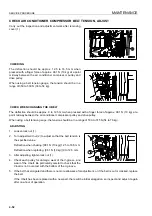
Страница 252: ...ible to use the frame lock bar as a step For details of the oil to use see USE OF FUEL COOL ANT AND LUBRICANTS ACCORDING TO AMBIENT TEMPERATURE 4 12 4 If the oil level is above the A mark on sight gau...

Страница 253: ...oil level is near the bottom of the plug hole 5 If the oil is not near the bottom edge of the hole add oil through oil filler F 6 If the oil level is correct install level plug 1 Tightening torque 127...

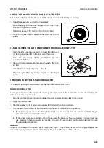
Страница 254: ...on cover 1 on the floor surface then remove 3 bolts from cover 2 at the air conditioner con denser portion 2 Remove any mud or dirt stuck to the condenser then wash with water If the water pressure is...

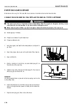
Страница 255: ...nozzle between oil cooler 2 and radiator assembly 3 and use compressed air to blow out the mud or dirt out to the front and rear of the machine 4 If the mud or dirt cannot be removed from aftercooler...

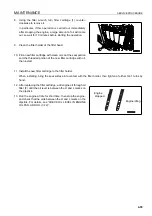
Страница 256: ...r protective equipment BUCKET WITH TIP TOOTH Replace the teeth before they wear down as far as the adapter 1 Raise the bucket to a suitable height then put blocks under the bucket to keep the bottom o...

Страница 257: ...quipment control lever is heavy or does not move smoothly apply grease If the AJSS lever is heavy or stiff when adjusted to the front or rear lubricate the U joint 2 AJSS lever U joint Carry out greas...

Страница 258: ...efrigerant circuit 1 Start the engine 2 Run the air conditioner at maximum cooling 3 Open the cover at the rear of the operator s compartment 4 Look at the sight glass inspection window of the receive...

Страница 259: ...utes or more after the engine is started 4 Stop the engine 5 Remove the air bleeder cap from the brake housing and insert one end of a vinyl hose in the brake housing and put the other end in a contai...

Страница 260: ...the power OFF when replacing the slow blow fuse turn the starting switch to the OFF posi tion q Always replace the slow blow fuse with a fuse of the same capacity 1 Turn the starting switch to the OFF...

Страница 261: ...off until the air is completely bled from the piston pump 1 Before starting up the engine loosen plug 1 installed above the tube on the suction side of the piston pump There is a plug on each pump so...

Страница 262: ...ir bleed plug 1 to bleed the air from the hydraulic tank After bleeding the air tighten plug 1 again 4 Check the hydraulic oil level and ensure that is correct Refer to CHECK OIL LEVEL IN HYDRAULIC TA...

Страница 263: ...locknut 2 then loosen the adjustment bolt 1 and remove it from yoke 3 with locknut 2 still fitted There is danger of losing parts so do not remove bolt 1 from bracket 4 2 Use an adjustable wrench whe...

Страница 264: ...of the tension pulley 5 and the end face of the oblong hole of yoke 3 is 0 mm then tighten a further 6 turns Lock securely with locknut 2 After operating for 1 hour if there is a gap between pin 6 of...

Страница 265: ...e machine Use only specified tires and inflate them to the specified pressure Select the tires according to the conditions of use and the weight of the attachments of the machine Use the fol lowing ta...

Страница 266: ...erve the specified inflation pressure Do not adjust the inflation pressure of the tires just after high speed travel or heavy duty work CHECK Measure the inflation pressure with a tire pressure gauge...

Страница 267: ...q Check dust indicator q Drain water from fuel pre filter q Check coolant level add coolant q Check oil level in engine oil pan add oil q Check brake oil tank level add oil q Check fuel level add fuel...

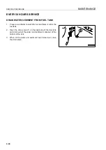
Страница 268: ...TANK 4 1 Prepare a container to catch the fuel and place it under the fuel tank 2 Open the drain valve 1 on the right side of the fuel tank and drain out all the water and sediment collected at the b...

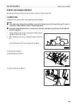
Страница 269: ...s 1 through 6 every 10 hours of operation or daily whichever way is deemed appropriate q During the initial breaking in for a new machine carry out ubrication every 10 hours for the first 50 hours of...

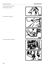
Страница 270: ...SERVICE PROCEDURE MAINTENANCE 4 46 4 Backet cylinder pin 2 places 5 Bellcrank pin 1 place 6 Lift cylinder pin 4 places 7 Steering cylinder pin 4 places...

Страница 271: ...cket to the ground stop the engine and wait for approx 5 minutes 2 Check the oil level with sight gauge G of the hydraulic tank The oil level should be near the top of sight gauge G NOTICE If the oil...

Страница 272: ...e cleaned Stop the air conditioner before cleaning the element 1 Stop the engine 2 Grip the handle 1 and open the cover 2 3 Loosen screw 3 then take out element 4 and clean it 4 Direct dry compressed...

Страница 273: ...rrode other parts NOTICE If there is danger of the electrolyte freezing if distilled water is added add the distilled water before start ing operations on the next day Inspect the battery electrolyte...

Страница 274: ...ge and poles appear bent q B Low Electrolyte level is not up to bottom of sleeve 2 so poles appear straight and not bent 2 After adding distilled water tighten cap 1 securely REMARK If water is added...

Страница 275: ...sion so that the deflection is approx 20 mm when pressed with a finger force of approx 58 8 N 6 kg 3 After adjusting tighten locknut 2 and bolt 1 4 Check each pulley for damage wear of the V groove an...

Страница 276: ...r compressor pulley and drive pulley When using a belt tension gauge the tension should be in a range of 530 to 745 N 54 to 76 kg ADJUSTING 1 Loosen lock nut 1 2 Turn adjustment nut 2 to adjust so tha...

Страница 277: ...For details of handling the accumulator see Section ACCUMULATOR 2 36 BRAKE ACCUMULATOR If the engine stops when the machine is traveling the oil pressure in the accumulator can be used to apply the br...

Страница 278: ...Refill capacity 130 liters q Prepare a container to catch drain fuel q Prepare a filter wrench 1 Stop the engine and wait for the temperature at all parts to go down 2 Open the engine side cover on t...

Страница 279: ...he threaded portion of the new filter cartridge with oil then install 11 Install the new filter cartridge to the filter holder When installing bring the seal surface into contact with the filter holde...

Страница 280: ...fuel may spurt out NOTICE q Genuine Komatsu fuel filter cartridges use a special filter that has highly efficient filtering ability When replacing the filter cartridge always use a genuine Komatsu pa...

Страница 281: ...hen adding fuel Be careful not to let dirt or dust get into center portion on the clean side 6 When installing tighten until the packing surface contacts the seal surface of the filter holder then tig...

Страница 282: ...e brake component box 3 Set a container under filter case 3 to catch the oil 4 Remove drain plug 4 at the bottom of the filter case drain the oil then tighten the plug again 5 Loosen hexagon part 5 of...

Страница 283: ...when the following conditions exist replace or adjust the V belt q When there is a clearance between the tension pulley lever and tip of the adjustment screw q When the V belt makes contact with the...

Страница 284: ...elease the internal pressure then remove it q Refill capacity 140 liters 1 Stop the engine and wait for the temperature at all parts to go down 2 Set a container to catch the oil under drain plugs 1 a...

Страница 285: ...pecified amount of engine oil from oil filler F 11 After filling with oil check that the oil is at the specified level For details see CHECK TRANSMISSION OIL LEVEL ADD OIL 4 28 12 Check that there is...

Страница 286: ...ail fuel injection system used on this machine consists of more precise parts than the conventional injection pump and nozzle If any part other than a genuine Komatsu filter cartridge is used dust or...

Страница 287: ...el If the filter cartridge is too loose fuel will also leak from the packing so always tighten the correct amount 8 After replacing fuel filter cartridge 2 bleed the air For details see PROCEDURE FOR...

Страница 288: ...shed out Applicable for machines with no auto greasing system installed to positions 1 2 or 7 1 Center hinge pin 2 places CAUTION If you fail to grease the drive shaft the shaft will break and there i...

Страница 289: ...MAINTENANCE SERVICE PROCEDURE 4 65 3 Front drive shaft 3 places 4 Rear drive shaft 2 places 5 Upper drive shaft 3 places 6 Parking brake linkage 6 places...

Страница 290: ...high pressure greasing TIGHTEN ROPS CANOPY 4 1 Loosen the bolt then remove the cover 2 Check that there is no looseness in mounting bolts 1 of the ROPS canopy If any bolt is loose tighten it Tighteni...

Страница 291: ...over on the left side of the machine 3 Close valve 2 on top of corrosion resistor 1 4 Using a filter wrench turn cartridge 2 to the left to remove it 5 Clean the filter holder of the filter head coat...

Страница 292: ...of the hoses between air cleaner A and turbocharger B Tighten any loose clamps Check for any looseness in clamps 3 and 4 of the hoses between turbocharger B and aftercooler C and the engine Tighten an...

Страница 293: ...work q When removing the oil filler cap turn it slowly to release the internal pressure then remove it q Refill capacity 725 liters 1 Set the bucket horizontally on the ground then turn the parking br...

Страница 294: ...6 and bypass valve 7 then take out ele ment 8 11 Check that there is no foreign material inside the tank then clean it 12 Fit a new O ring to filter cover 4 13 Install the new element then set bypass...

Страница 295: ...ediately after startup or a cylinder is pushed up to its stroke end air taken inside the cylinder may cause damage to the piston packing 23 Next operate the steering bucket and lift arm cylinders to t...

Страница 296: ...ing oil If strainer 8 is broken replace it with a new part 4 Install spring 7 strainer 8 and cover 6 When doing this look through the mounting hole of cover 4 to check that the strainer guide pin is f...

Страница 297: ...ait for the temperature at all parts to go down 3 Open the cover on the right side of the operator s compart ment 4 Remove the cap of oil filler F 5 Remove the snap ring from breather 1 then remove th...

Страница 298: ...mperature to go down before starting the work q When removing the plug oil may spurt out so turn the plug slowly to release the internal pressure then remove it carefully q Refill capacity front and r...

Страница 299: ...4 and drain the oil 5 After draining the oil clean drain plugs 2 3 and 4 then install them 6 Add oil to the specified level through the oil filler ports 1 and 5 of the axle housing and left and right...

Страница 300: ...the left side of the cab then remove the cap from oil filler F Pull knob 5 of the cap of oil filler F then turn the cap counterclockwise to remove it 4 Loosen drain valve 3 slowly and drain the oil 5...

Страница 301: ...ip 1 pulled turn cap F counterclockwise and remove it 2 Remove mounting bolts 3 of filter cover 2 then remove the cover When doing this the cover may spring out under the force of spring 4 so hold the...

Страница 302: ...tion air filter and fresh air filter in the same way as when cleaning and replace them with new parts For details of cleaning the recirculation air filter see CLEAN ELEMENT IN AIR CONDITIONER RECIRCUL...

Страница 303: ...il pressure Start the engine then check that the brake oil pressure caution pilot lamp and the central caution lamp CAUTION are flashing but that the warning buzzer is not sounding intermittently 1 Re...

Страница 304: ...on 5 Check that the area around the machine is safe then turn the starting switch to the ON position set the lift arm con trol lever to FLOAT position d and lower the work equip ment to a point 1 m ab...

Страница 305: ...roblem is found contact your Komatsu distributor for disassembly and repair or replacement CHECK STARTING MOTOR 4 The brush may be worn or have no grease on the bearing so contact your Komatsu distrib...

Страница 306: ...arts If any problem is found the part must be replaced In this case please ask your Komatsu distributor to carry out the replacement NOTICE If the engine continues to be used when there are loose bolt...

Страница 307: ...nt fire caused by fuel leaking and spray ing out on to high temperature parts of the engine Check visually that there are no missing caps or loose bolts and feel with your finger to check that the rub...

Страница 308: ...at the same time REPLACE ENGINE HIGH PRESSURE PIPING CLAMPS 4 Contact your Komatsu distributor to have the engine high pressure clamps replaced REPLACE FUEL SPRAY PREVENTION CAP 4 Contact your Komats...

Страница 309: ...SPECIFICATIONS 15...

Страница 310: ...th mm 13960 14485 B Overall height mm 5275 C Bucket overall height When bucket lifted mm 9300 9680 D Overall width mm 4585 E Min ground clearance mm 550 F Bucket width Tire guard Tip of tooth mm 5045...

Страница 311: ...ATTACHMENTS OPTIONS 16 WARNING Please read and make sure that you understand the SAFETY section before reading this section...

Страница 312: ...Spade nose bucket 11 0 m3 General ground conditions 45 65 45 46PR L5 45 65 45 50PR L5 Hard ground Ground with many boulders 45 65 45 46PR L5 45 65 45 50PR L5 Use tire chains as a tire protector Soft g...

Страница 313: ...at auto greasing pilot lamp 5 on the main monitor lights up Lamp lights up Normal Electricity is supplied to the auto greasing system and when there is no abnormality and the grease pump is being actu...

Страница 314: ...tes only while the auto greasing switch is kept pressed The grease pump stops immediately when the auto greasing switch is released This switch is used mainly to check the operation of the grease pump...

Страница 315: ...tch This work shall be performed by two persons 1 Open transmission inspection cover 5 at the rear of the cab One person removes pressure switch 7 from block 6 then stays there 2 The other person pres...

Страница 316: ...ng 10 of injector 9 then fill the all branch lines with grease by using a hand grease gun 7 Check of supply line pressure Check grease pump pressure gauge 12 and supply grease line pressure gauge 13 S...

Страница 317: ...ATTACHMENTS OPTIONS HANDLING AUTO GREASING SYSTEM 6 7 8 Check of operation of injector Turn ON the auto greasing switch and check that indicator pin 14 of injector SL 1 SL 11 is operating normally...

Страница 318: ...cylinder rod Right and left 7 8 Open fully 3 9 Close by 5 turns from full 3 9 Keep at position for sec ond step 8 Boom cylinder bot tom Right and left 7 8 Open fully 3 9 Close by 5 turns from full 3 9...

Страница 319: ...EASING SYSTEM 6 9 Greasing points Loader linkage Section Q Section P right side of machine body Right Left Left Right 1 Bucket hinge 4 Bucket cylinder rod 2 Bucket link front 6 Bellcrank center 3 Buck...

Страница 320: ...frame side Left Right Left Right Right Right Left Left 5 Bucket cylinder bottom 13 Center hinge pin lower 8 Lift arm cylinder bottom 14 Rear axle support front 9 Lift arm pivot right 15 Transmission...

Страница 321: ...justment screw 3 clockwise If the adjustment screw stops at the stopper the discharge is minimized 2 If the adjustment screw is returned by 10 turns from the fully tightened position minimum discharge...

Страница 322: ...the discharge is minimized 2 If the adjustment screw is returned by 10 turns from the fully tightened position minimum discharge in 1 above the discharge is maximized 8 2 cc st After adjusting the di...

Страница 323: ...ing Examine When timer is set to 11 25 minutes 1 Adjustment of greasing interval Timer box 1 is in the position shown at right q Power supply for timer Even after the starting switch is turned off bot...

Страница 324: ...e and operating time To adjust the interval time turn blue rotary switch 1 in the figure at right according to the following table 1 Set the blue dial to division 3 after the auto grease system is ins...

Страница 325: ...ix this dial to position 8 60 seconds 1 Set the red dial to division 8 For normal operation 2 When greasing is finished and the greasing pump is balanced the greasing pump stops even if within the spe...

Страница 326: ...engine before charging with grease Charge with grease from coupler 1 at the center hinge por tion When it is fully charged with grease red indicator 2 lights up Indicator 2 lights up even when the st...

Страница 327: ...inside of grease pump case 4 with grease When using a pail can replace the pail can 4 Install follower plate 3 and grease pump 2 to grease pump case 4 then tighten with bolts 1 The applicable followe...

Страница 328: ...so it is necessary to obtain authorization and conform to the laws of the country or territory where the machine equipped with VHMS is being used Always contact your Komatsu distributor before selling...

Страница 329: ...hine is outside it cannot be used in areas where the radio signal is weak or in areas outside the wireless communication service area There is absolutely no need to inspect or operate the VHMS or comm...

Страница 330: ...HANDLING MACHINES EQUIPPED WITH VHMS ATTACHMENTS OPTIONS 6 20...

Страница 331: ...INDEX 17...

Страница 332: ...INDEX 7 2...

Страница 333: ...N HANDLING AUTO GREASING SYSTEM 6 4 HANDLING CAB WIPER 3 46 HANDLING MACHINES EQUIPPED WITH VHMS 6 18 VHMS AND COMMUNICATIONS TERMINAL INSTALLED 6 18 VHMS INSTALLED COMMUNICATIONS TERMINAL NOT INSTALL...

Страница 334: ...00 HOURS SERVICE 4 69 EVERY 250 HOURS SERVICE 4 49 EVERY 4000 HOURS SERVICE 4 81 EVERY 50 HOURS SERVICE 4 44 EVERY 500 HOURS SERVICE 4 54 EVERY 8000 HOURS SERVICE 4 84 INITIAL 250 HOURS SERVICE 4 21 W...

Страница 335: ...COLOPHON 18...

Страница 336: ...COLOPHON 8 2 WA800 3E0 WA900 3E0 GALEO WHEEL LOADER Form No EEAM026100 2007 KOMATSU All Rights Reserved Printed in Belgium 03 07...

Отзывы:

Похожие инструкции для WA800-3E0