INSTRUMENTS AND CONTROLS
112
4
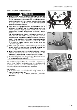
JOYSTICK STROKE ADJUSTING KNOB
WARNING
q
The adjustment of the joystick stroke must be carried out
before starting work and with the machine completely still.
q
Before carrying out this operation make sure that the servo
control locking button is in locking position (LED on) (see
"3.3.2 pos. 12 - SERVO CONTROL LOCKING BUTTON").
These knobs are positioned on the cab floor, on the front part of
each joystick support. They serve to adjust the stroke of both
joysticks in operating position.
For the adjustment, proceed as follows:
1 - After releasing the joysticks, lower them completely until
reaching the end of stroke. If they are excessively inclined,
reduce the stroke by turning the knobs (4) clockwise, as
indicated by the arrow (A).
If, on the other hand, it is necessary to increase the stroke in
order to obtain a more inclined position of the joysticks, turn
the knobs (4) counterclockwise, as indicated by the arrow
(B).
2 - After adjusting both joysticks, make sure that their position is
within the desired values.
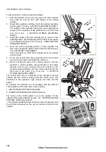
It is also possible to adjust the stroke of the joysticks when they
are not used and are in vertical position. Once they have been
lifted, make sure that the safety distance between the joystick (C)
and the rear window (D) is sufficient to avoid any contact
(approximately 60 mm).
If an adjustment should be necessary, proceed as follows:
1 - To increase the distance between the joystick (C) and the
rear window (D), loosen the stop nut (E) and turn the
adjusting screw (F) clockwise.
To decrease the distance between the joystick and the rear
window, turn the adjusting screw (F) counterclockwise.
Use a 17 mm hex wrench.
2 - Make sure that the distance complies with the safety limits
and tighten the stop nut (E) thoroughly.
IMPORTANT
q
The joysticks must always be turned moderately, trying to
accompany them until they reach the desired position.
q
After adjusting the stroke of both joysticks, make sure that
all fastening elements are correctly tightened.
RKA15420
4
2
A
B
RKA15430
4
RKA15440
60 mm
C
D
RKAB4860
E
F
https://tractormanualz.com
Содержание Utility WB97S-5
Страница 2: ...https tractormanualz com ...
Страница 21: ...SAFETY AND ACCIDENT PREVENTION 19 https tractormanualz com ...
Страница 64: ...62 THIS PAGE WAS INTENTIONALLY LEFT EMPTY https tractormanualz com ...
Страница 65: ...THE MACHINE AND ITS OPERATIONS 63 https tractormanualz com ...
Страница 164: ...162 THIS PAGE WAS INTENTIONALLY LEFT EMPTY https tractormanualz com ...
Страница 165: ...MAINTENANCE 163 https tractormanualz com ...
Страница 233: ...TECHNICAL SPECIFICATIONS 231 https tractormanualz com ...
Страница 239: ...TECHNICAL DATA 237 5 1 3 3 LIFTING CAPACITIES BOOM WITH OFFSET DEVICE https tractormanualz com ...
Страница 240: ...238 THIS PAGE WAS INTENTIONALLY LEFT EMPTY https tractormanualz com ...
Страница 241: ...AUTHORISED OPTIONAL EQUIPMENT 239 https tractormanualz com ...
Страница 279: ...https tractormanualz com ...
Страница 280: ... 2006 KOMATSU UTILITY EUROPE S p A All Rights Reserved Printed in Europe 02 2006 https tractormanualz com ...


